The Computer Laboratory Relics Database
The database contains details of over 200 artifacts ranging from turn of the century calculating machines, through pieces of our early electronic machines (EDSAC I and II), to bits and pieces built for specific research projects, or extracted from interesting commercial machines.
There are also still significant holes in the database, being filled as time permits. All information and photographs produced by this Search facility are subject to the departmental Relics Project copyright and license terms.
Unique id/year of acquisition: CL-11/97
Name: Ring monitor station
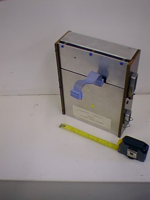
Other No marked on object:
Inscription:
Dimensions: 213x161x72
Description:
Class: network
Machine name: Ring
Condition:
Notes: DW: Around 1968 the Lab developed an inter-communication ring through the Laboratory. Essentially information flowed round twisted-pair wires and all stations were in series. There was one special station which is the monitor station which set up a pattern which allows packets to be transmitted or received at individual stations. The packets were quite small - they held two bytes. The main purpose was not to provide rapid speed but to provide inter-communication between printers, computers etc for which speed didn't matter particularly. The monitor station was used to set up - it also kept continual check on the ring to make sure that it was working properly and it also gathered some statistics. It was an essential part of the ring but there was only one of the these and it allowed design changes to be incorporated here rather than in every individual station so it did give us some flexbility.
Q: Who was behind the design of the ring in the laboratory?
DW: Maurice Wilkes initiated it - I with Norman Unwin designed it and there were two versions - the first version we threw out not because it didn't work but because the next was rather simpler and would work better under failure modes. The second version was made by units of this size, by then small scale integrated circuits were used and I think there were about maybe 50 such integrated circuits in. The power supplies were designed by Unwin and it was interesting that the power for every station on the ring came from one source along the same lines which took the signals, so they were independent of the mains in any particular position.
Q:Was this produced locally in Cambridge?
DW: Yes, it was. The early ones were hand-wired. I believe some were sent out to an automatic wiring machine for specification, but basically they were produced in the Lab. And this was a later version.
Correction from Martyn Johnson: this is not actually a monitor station; it is merely the repeater that was used at the monitor station position. I think it was different from the others in some way; though I can't remember in what respect.
See also: CL-41/97
See also: CL-48/97
See also: CL-110/99
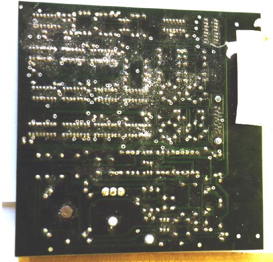
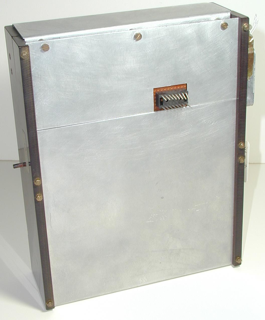
Unique id/year of acquisition: CL-32/97
Name: Ring repeater
Other No marked on object: none
Inscription: Sation Logic Mk.3 Serial No. 01 (on sticker)
Dimensions: 212x160x58
Description: Grey metal box with brown Bakelite (?) edges. One edge has 2 2x25 plugs and a few other holes. At one end of large face is a 16-way ribbon cable. PCBs visible inside through gaps in casing.
Class: network
Machine name: Ring
Condition: good
Notes: DW: These are 2 components of the Cambridge ring. They were repeaters. The Cambridge ring consisted of a pair of twisted wires which were taken round the Lab and they plugged into one of these devices. This device would regenerate the pulses and allow some device which accepted or gave information to be attached to the ring. A particular ring would have up to 256 different repeater elements and each was numbered and it used the packet system whereby a packet held source number, destination number and 2 bytes of information plus about 5 control bits which indicated the starts of packets and various other information, whether the packet was full or empty and so. These were designed in the Lab but they were wire-wrapped by an outside firm and the construction inside is small scale integrated circuits where the circuit containing at the most about a 4 bit shift register which could be loaded parallel- or serial-wise and if I remember correctly there is about 40 or 50 such circuits in one these boxes. In addition there were some straight forward transistors for generating the power supplies inside from the ring itself and for detecting the incoming pulse and converting it and generating the clock. These were in use a number of years. In fact I believe the last one to be used is supposedly at the University of Hertfordshire which was disconnected 2 or 3 years ago. So they had a fair life.
Q: When were they first used/ first designed?
DW: They were first designed 1978. There was an old version which used the package injection technique. These were modified ones which allowed for easier maintenance and automatic diagnosis of faulty repeaters These were ones which we standardised on throughout the Lab. It became a UK standard and supplied to many universities throughout the UK.
Q: You say they were designed in the Lab - who was responsible for that?
DW: I designed these - though to some extent it was collaborative for various design decisions taken in collaboration with other people. But the individual design of this and of course of computers as design automation for generating the wiring which was sent to outside suppliers who used automatic wire-wrapping machines which were then available.
See also: CL-33/97
See also: CL-101/99
See also: CL-111/99
Unique id/year of acquisition: CL-33/97
Name: Ring repeater
Other No marked on object: none
Inscription: Repeater Mk.3 Serial No.01 (on sticker), Good spare 20/5/85 (on sticker)
Dimensions: 211x160x59
Description: Grey metal box with brown Bakelite (?) edges. One edge has 1 15-way D-type plug and a few other holes. At one end of large face is a 16-way plug. PCBs visible inside through gaps in casing.
Class: network
Machine name: Ring
Condition: good
Notes: DW: These are 2 components of the Cambridge ring. They were repeaters. The Cambridge ring consisted of a pair of twisted wires which were taken round the Lab and they plugged into one of these devices. This device would regenerate the pulses and allow some device which accepted or gave information to be attached to the ring. A particular ring would have up to 256 different repeater elements and each was numbered and it used the packet system whereby a packet held source number, destination number and 2 bytes of information plus about 5 control bits which indicated the starts of packets and various other information, whether the packet was full or empty and so. These were designed in the Lab but they were wire-wrapped by an outside firm and the construction inside is small scale integrated circuits where the circuit containing at the most about a 4 bit shift register which could be loaded parallel- or serial-wise and if I remember correctly there is about 40 or 50 such circuits in one these boxes. In addition there were some straight forward transistors for generating the power supplies inside from the ring itself and for detecting the incoming pulse and converting it and generating the clock. These were in use a number of years. In fact I believe the last one to be used is supposedly at the University of Hertfordshire which was disconnected 2 or 3 years ago. So they had a fair life.
Q: When were they first used/ first designed?
DW: They were first designed 1978. There was an old version which used the package injection technique. These were modified ones which allowed for easier maintenance and automatic diagnosis of faulty repeaters These were ones which we standardised on throughout the Lab. It became a UK standard and supplied to many universities throughout the UK.
Q: You say they were designed in the Lab - who was responsible for that?
DW: I designed these - though to some extent it was collaborative for various design decisions taken in collaboration with other people. But the individual design of this and of course of computers as design automation for generating the wiring which was sent to outside suppliers who used automatic wire-wrapping machines which were then available.
See also: CL-32/97
See also: CL-101/99
See also: CL-111/99
Unique id/year of acquisition: CL-34/97
Name: Ring PCB
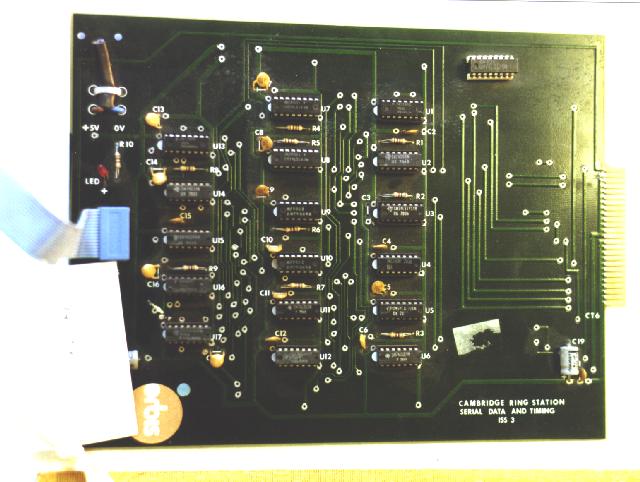
Other No marked on object: none
Inscription: "Cambridge ring station data and timing ISS3", "ORBIS" (on sticker)
Dimensions: 252x185x10
Description: Rectangular green PCB with insertion strips (25) protruding from one edge. Selection of chips, a few other components. Blue 16-way ribbon cable attached on one side, power cable (2-way, 0V and +5V) soldered to rear, cut off.
Class: network
Machine name: Ring
Condition: good
Notes: DW: These are two circuit boards connected with the Cambridge ring. Later versions of the ring had more integrated circuits - in fact one circuit was designed especially by Andy Hopper to replace nearly all the chips on the previous boards. This was then possible - it was made to work but it never came into service here because it would only run safely at about 7 megahertz and not 10 megahertz mainly due to doubtful specifications by manufacturers. Both of these boards have a single chip which does the hard part of the Cambridge ring. This fat transformer is still used for generating the power supply for the board from the ring and this is a transistor and as you can see it has a large heat sink on because it handles the power to supply the rest of the board.
Q: So these boards are from the later life of the ring?
DW: When the ring was in service it was thought you could replace the entire board by a single integrated circuit which was possible. We went to an extraordinary amount of trouble. One manufacturer failed and another manufacturer refused to manufacture them, and so there was a lot of hassle and they were never really satisfactory. They turned up too late to be really useful.
Q: So these boards would date from roughly when?
DW: Probably about 2 - 5 years after the Ring started. I'm not quite sure about these. Certain manufacturers went into manufacture for Ring components and there was a specification by British standards to which they adhered.
See also: CL-35/97
See also: CL-103/99
Unique id/year of acquisition: CL-34/97
Name: Ring PCB
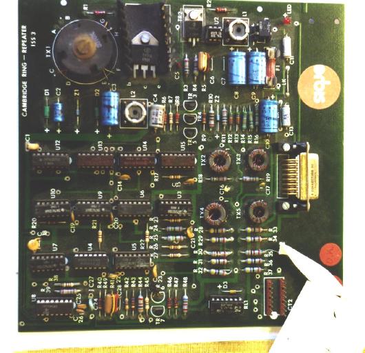
Group id: 2
Other No marked on object: none
Inscription: "Cambridge ring - repeater ISS3","ORBIS" (on sticker)
Dimensions: 187x185x25
Description: Green PCB, variety of chips and other components inc. large transformer (?), large heat sink, plug (15-way D type), several chips.
Class: network
Machine name: Ring
Condition: rear corroded
Notes: DW: These are two circuit boards connected with the Cambridge ring. Later versions of the ring had more integrated circuits - in fact one circuit was designed especially by Andy Hopper to replace nearly all the chips on the previous boards. This was then possible - it was made to work but it never came into service here because it would only run safely at about 7 megahertz and not 10 megahertz mainly due to doubtful specifications by manufacturers. Both of these boards have a single chip which does the hard part of the Cambridge ring. This fat transformer is still used for generating the power supply for the board from the ring and this is a transistor and as you can see it has a large heat sink on because it handles the power to supply the rest of the board.
Q: So these boards are from the later life of the ring?
DW: When the ring was in service it was thought you could replace the entire board by a single integrated circuit which was possible. We went to an extraordinary amount of trouble. One manufacturer failed and another manufacturer refused to manufacture them, and so there was a lot of hassle and they were never really satisfactory. They turned up too late to be really useful.
Q: So these boards would date from roughly when?
DW: Probably about 2 - 5 years after the Ring started. I'm not quite sure about these. Certain manufacturers went into manufacture for Ring components and there was a specification by British standards to which they adhered.
See also: CL-35/97
See also: CL-103/99
Unique id/year of acquisition: CL-35/97
Name: Ring PCB (experimental)
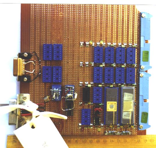
Other No marked on object: none
Inscription: none
Dimensions: 190x185x30
Description: Plug board with rows of blue component insertion blocks, two of which are used. Two large chips, one with top removed. 2 blue plugs (2x25) on one edge, 1 plug (15-way D type) and 1 socket (9-way D type) on other. rear of board wire-wrapped (badly !) with a number of additional wires and components.
Class: network
Machine name: Ring
Condition:
Notes: DW: This is an example of a good experimental set up and enormous number of holes in which you could push components and places for integrated circuits. The circuits being tested here were these large ones which which were made especially. The exact details of the board I forget. In this case this no doubt was the manufactured chip and the rest was to test it. That's all I can say.
See also: CL-34/97
See also: CL-103/99
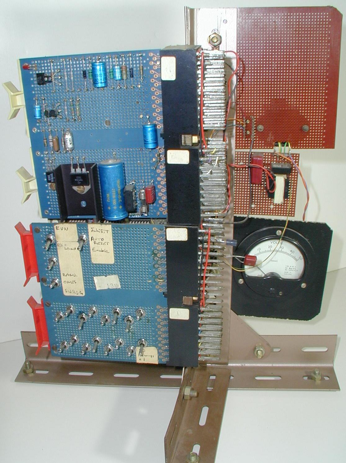
Unique id/year of acquisition: CL-39/97
Name: Ring data logger
Other No marked on object:
Inscription:
Dimensions:
Description:
Class: network
Machine name: Ring
Condition:
Notes: DW:This was part of the original experimental ring. This was a data logger in that it would detect errors and count them and display them and is used for diagnostics. Each station if it detected a parity fault, would automatically signal back to the monitor station which would cause it to be logged so that every failure could be logged and the ring could be maintained fairly readily. In practice it didn't need much maintenance and people forgot how things worked.
Q: This was from the early time of the Ring, so was it soon superseded by some other components?
DW: No, we kept on using our original components because they worked. Later ones looked better and were used for the second Ring and so on. But the original ones kept working, and we used them.
Unique id/year of acquisition: CL-40/97
Name: Ring power supply
Other No marked on object:
Inscription:
Dimensions:
Description:
Class: network
Machine name: Ring
Condition:
Notes: DW:This was a power supply for the Cambridge Ring. It has some relatively heavy components inside and it took ordinary mains voltages and converted it to 50 volts, and the 50 volts was sent along the two pairs of twisted wires - one voltage along one twisted wire, and the second voltage along the other, so each repeater could change the 50 volts into its own power supply for running its own circuits. This was an essential part- this had to be kept on all the time. The other repeater stations were independent of the mains and so it didn't rely on people switching on or not switching apparatus on.
Q: Was it like the other parts of Ring - designed here and made outside?
DW: Yes, it was designed by Norman Unwin and made in the workshop and it was rather an elegant design really, it saved us a lot of problems whether to power every individual station from the mains which would not have worked very well with people switching things on and off.
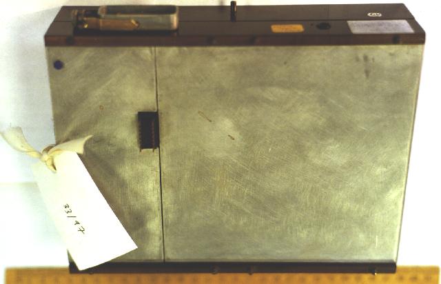
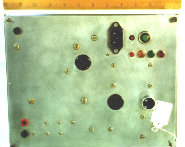
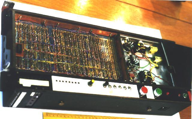
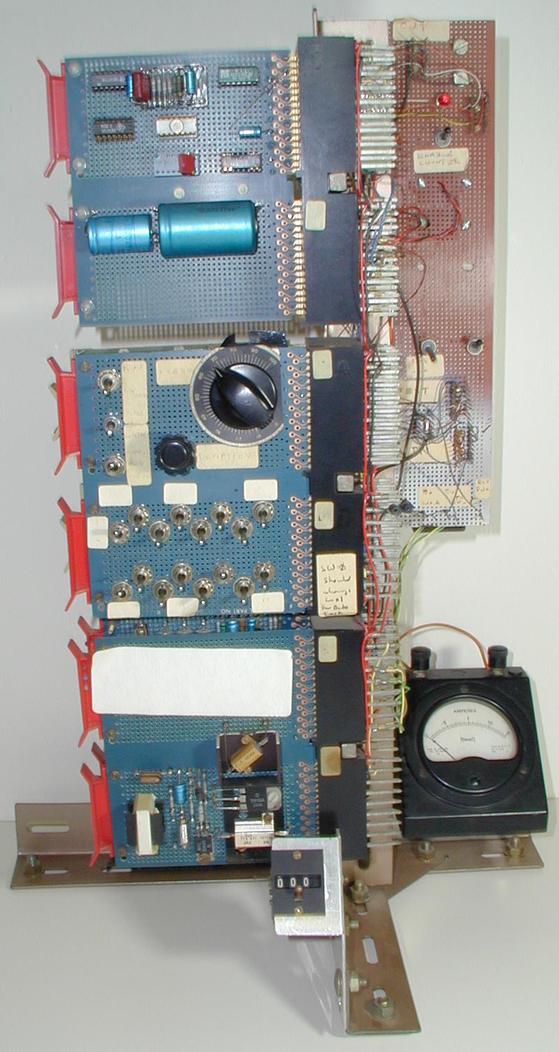
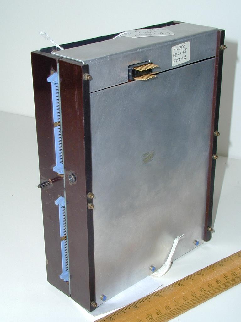
Unique id/year of acquisition: CL-41/97
Name: Ring monitor station
Other No marked on object: none
Inscription: many small printed labels
Dimensions: 583x375x100
Description: Black metal and plastic box. Carrying handles at ends. Top in three sections. On right with many switches, LEDs, a knob and two chips (?), many paper labels. Middle section has plastic window with printed paper information visible. This section slides back to reveal interior - much wire-wrapping, and power transistor. Small section at bottom with pins visible. Left narrow section of top with on and off buttons (so marked) and LED. Sockets and power plug input at left end.
Class: network
Machine name: Ring
Condition: good
Notes: DW: This was one of the so called monitor stations for the Ring. It set up a system of packets which were circulated right round the Ring, it detected when they came back, it checked that they came back correctly and it also controlled the turn-on sequence when the Ring was powered up initally by setting up the packet sequence and gaps between the end of the packet sequence and the start. It had a few testing circuits inside. It could also send random - fill empty packets with random data and check that if they came back empty the random data was correct. So it maintained a continuous check on the stability and working of the Ring. It was also used occasionally to make modifications which otherwise would have to be done in every single repeater right round the Ring. So it allowed minor updatings of design without particular inconvenience. On the front there is a description of a packet - there are various control switches which are mostly for engineers because once it was powered up it required no switch operation at all. But it did enable various tests to be made. It was a relatively big unit but fairly empty. There was a typical wire wrapping system which was used for inter-connections. In our case, unlike industrial people, we have colour coding on the wire, so it was fairly easy to trace. The box, although large is mainly empty - you can't see quite in, and this was held in the workshop to run on the Ring and it was hung on a wall. There is really very little else to say, it was just used as it says as a monitor of the Ring's performance and for starting it up.
Q: The label says 1980 - would that seem about the right date?
DW: Yes, I think we started on the Ring before then probably had something working but this is probably when this particular one was made which would not have been the first one when we were running the Ring.
Q: And did anyone design it in particular or was it a group effort?
DW: I think I did the logical design, Norman Unwin did the physical design and power supplies and things like that and it was made in the workshop.
See also: CL-11/97
See also: CL-48/97
See also: CL-110/99
Unique id/year of acquisition: CL-48/97
Name: Ring Monitor station
Other No marked on object:
Inscription:
Dimensions:
Description:
Class: network
Machine name: Ring
Condition:
Notes: DW:This object is the so-called ring monitor station which was part of the Cambridge Ring. It was an essential part. It supplied power to all the repeaters around the Ring. It provided start up facilities and monitored the Ring for accuracy and errors. Typically it was switched on and left working and it was possible to perform some tests on the Ring from this panel. And that's about all - it was just the power supply for the Ring and monitored if the power was supplied along the twisted pairs to all the individual repeaters.
Q: Was this in use throughout the lifetime of the Ring?
DW:Yes, it was an essential part of the Ring, although it evolved during the Ring because we could make changes at the monitor station without changing all the repeater stations. Access to the printed circuit board containing the components was behind this sliding panel. The mechanical part of this was designed by Norman Unwin.
See also: CL-11/97
See also: CL-41/97
See also: CL-110/99
Unique id/year of acquisition: CL-101/99
Name: Cambridge Ring repeater
Other No marked on object:
Inscription:
Dimensions:
Description:
Class: network
Machine name: Ring
Condition:
Notes: This is one component of the Cambridge Ring, a repeater. The Cambridge ring consisted of a pair of twisted wires which were taken round the Lab and they plugged into one of these devices - this allowed some device which accepted or gave information to be attached to the Ring. This device would regenerate the pulses. A particular Ring would have up to 256 such repeater elements. These were designed in the Lab but they were wire-wrapped by an outside firm. The Cambridge Ring was supplied to many universities throughout the UK - the last one to be used was at the University of Hertfordshire, disconnected only 2 or 3 years ago. The project started in 1974.
See also: CL-32/97
See also: CL-33/97
See also: CL-111/99
Unique id/year of acquisition: CL-102/99
Name: Ring Keyring
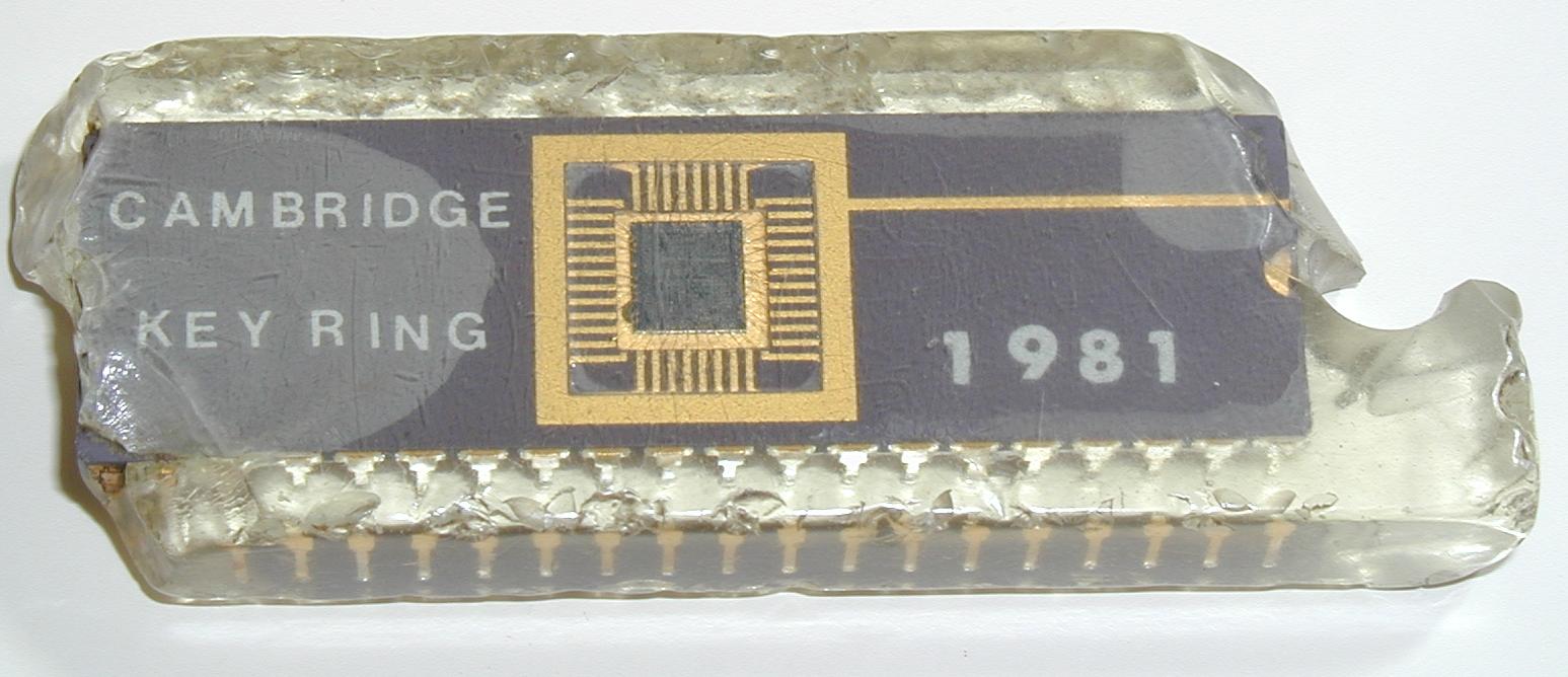
Other No marked on object:
Inscription:
Dimensions:
Description:
Class: network
Machine name: Ring
Condition:
Notes: A chip implementation of the Cambridge Ring was developed as part of a formal project under the Government's Advanced Computer Technology Projects. Some of the resulting chips were later made into commemorative key``rings''.
Unique id/year of acquisition: CL-103/99
Name: Ring circuits (experimental)
Other No marked on object:
Inscription:
Dimensions:
Description:
Class: network
Machine name: Ring
Condition:
Notes: Experimental boards produced during the development of the Ring.
See also: CL-34/97
See also: CL-35/97
Unique id/year of acquisition: CL-109/99
Name: Optlyne - Ring optical fibre interface
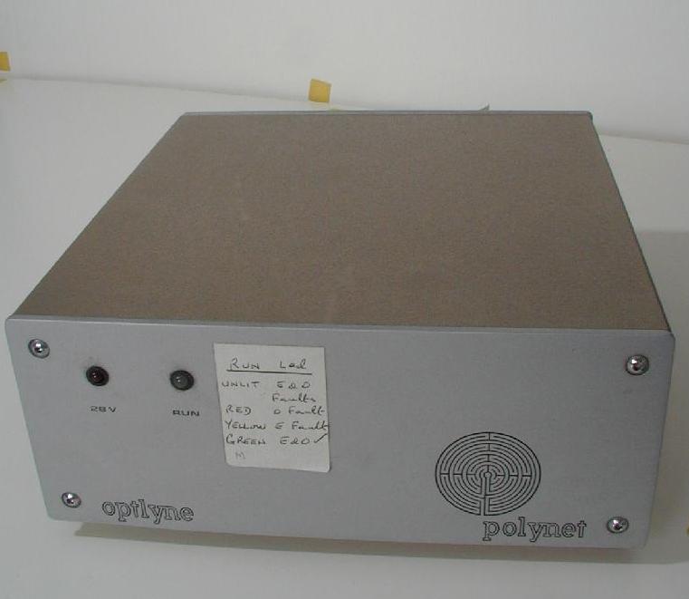
Other No marked on object: none
Inscription: "optlyne" and "polynet" with logo on front. "OPTLYNE D UNIT" "TYPE 225-02-0001-001" "Ser.No. 17771/13" "Logica VTS Ltd 64 Newman Streey London W1A 4SE England" "Manufactured for Logica VTS Ltd by DAC Ltd Burton-on-Trent Staffs England" all on label on back.
Dimensions: 228x218x95
Description: Buff-coloured metal box with silver front and rear. Front has 2 LEDs labelled 28V and RUN. Rear has D-type plug , two other sockets (optical fibre) and a large label. Sides have air vents.
Class: network
Machine name: Ring
Condition: good
Notes: Not used here, commercial implementation
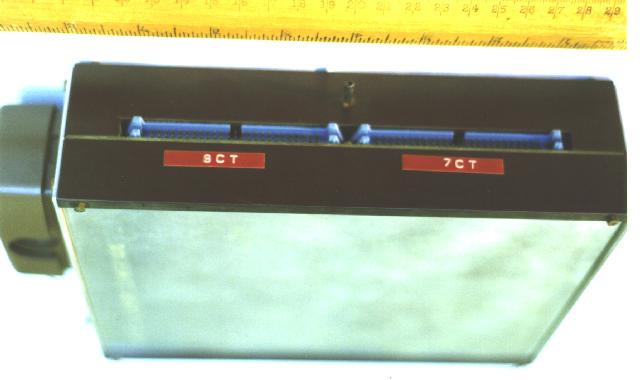
Unique id/year of acquisition: CL-110/99
Name: Early ring monitor station tester
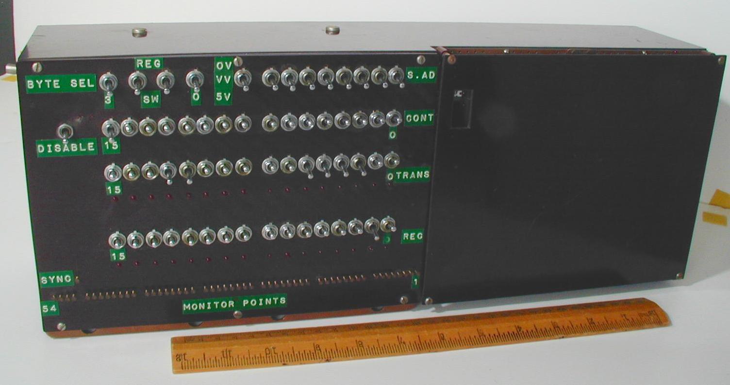
Other No marked on object: none
Inscription: none
Dimensions: 430x168x110
Description: Brown plastic case. One side has a power plug and a switch. long side has two 50-pin plugs. Top is in two parts: left side features 4 lines of switches, some of which have stuck on labels, two lines of LEDs, and a line of small brass screws at the bottom labelled MONITOR POINTS. The right side is blank apart from a small rectangular hole cut through. The rear is open showing wiring and 7 dangling ribbon cables of different sizes.
Class: network
Machine name: Ring
Condition: good
Notes:
See also: CL-11/97
See also: CL-41/97
See also: CL-48/97
Unique id/year of acquisition: CL-111/99
Name: Ring repeater mk 1
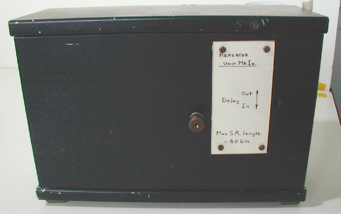
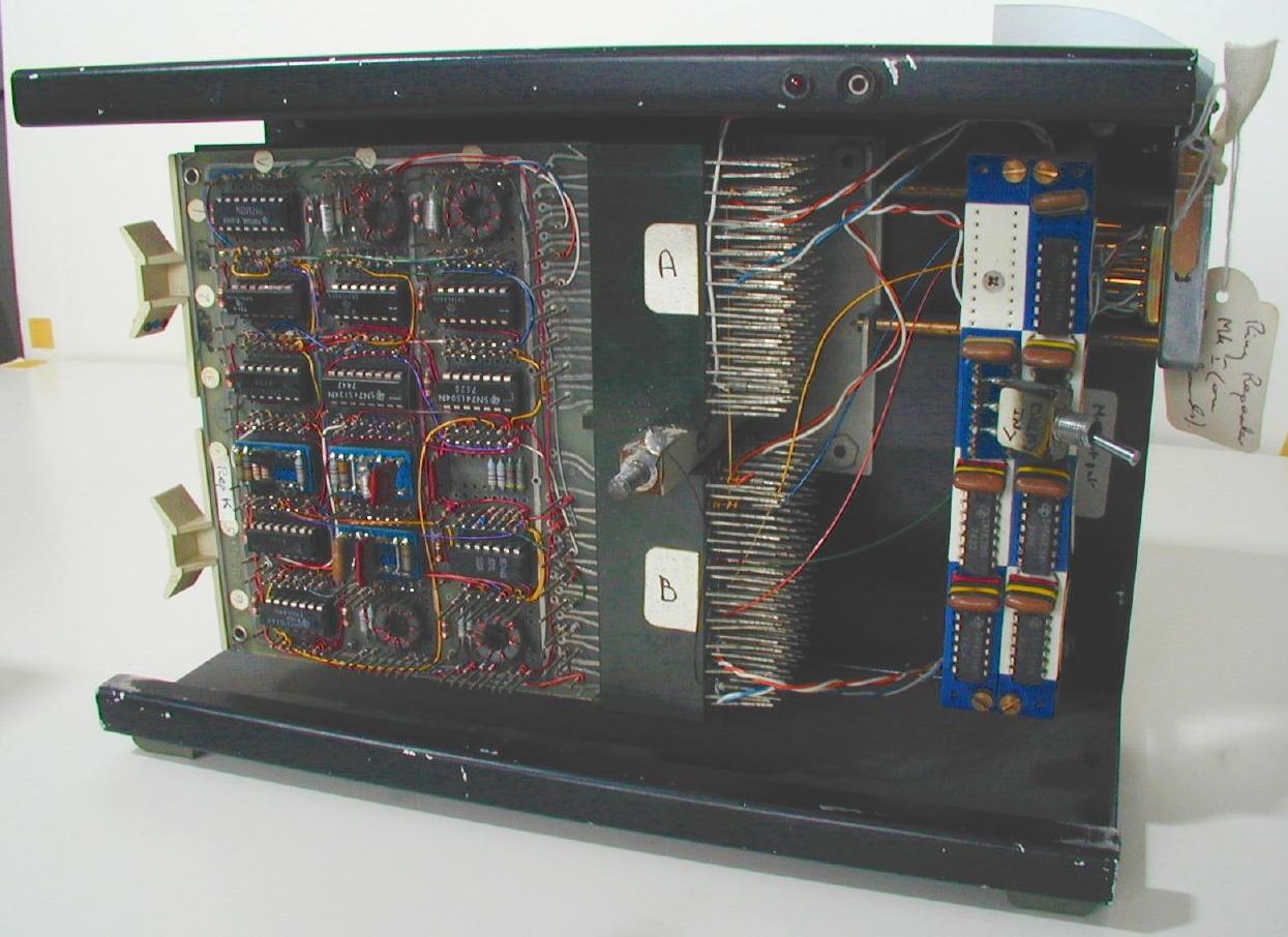
Other No marked on object: none
Inscription: REPEATER Mk. Ia With 40 bits S/Reg. serial No.3 (on sticker on rear), REPEATER UNIT MkIa (on front)
Dimensions: 255x180x100
Description: Black metal box, rubber feet on rear and bottom, D-type plug on right side. Front has screwed on label and brass screw holding front on (if removed this slides off to reveal interior wiring).
Class: network
Machine name: Ring
Condition: good
Notes:
See also: CL-32/97
See also: CL-33/97
See also: CL-101/99
Unique id/year of acquisition: CL-128/99
Name: Ring demo posters
Photograph not applicable
Other No marked on object: none
Inscription: none
Dimensions: various
Description: posters and photographs
Class: documentation
Machine name: Ring
Condition: good
Notes: 4 posters and 2 large similar photographs (the ring units inside the CAP).
Unique id/year of acquisition: CL-129/99
Name: UCL - 3 linked cards
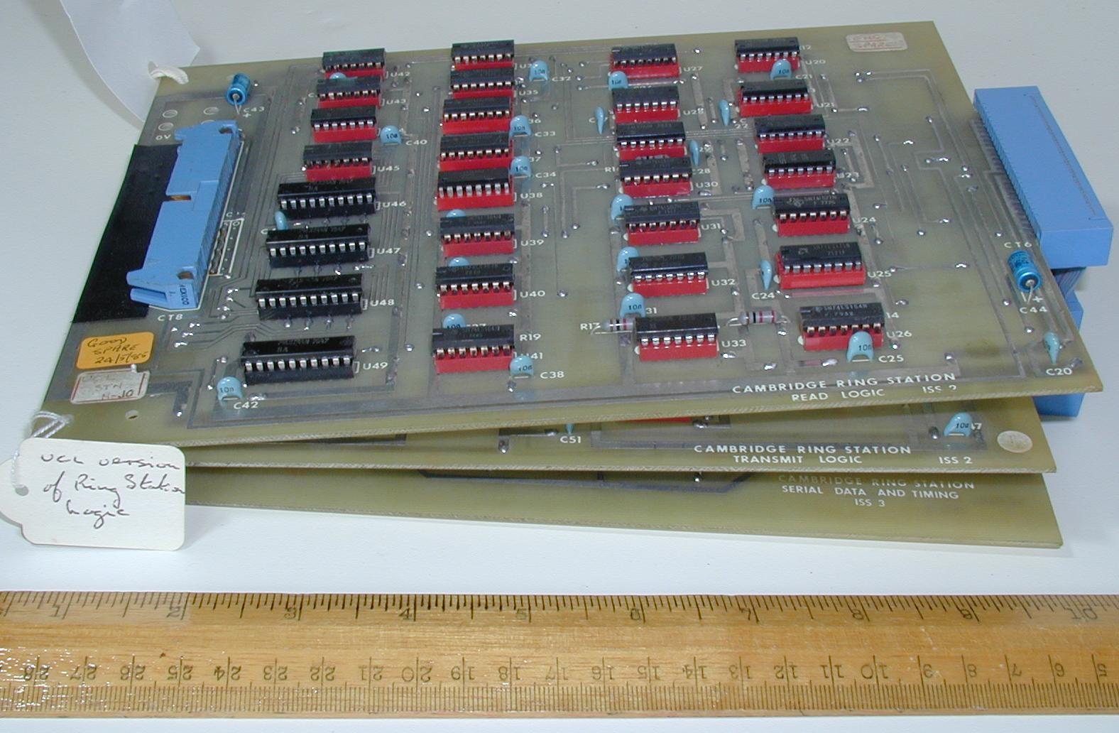
Other No marked on object: none
Inscription: GOOD SPARE 24/5/85 (sticker on top) CAMBRIDGE RING STATION READ LOGIC ISS 2 (embossed on top card) CAMBRIDGE RING STATION TRANSMIT LOGIC ISS 2 (embossed on middle card) CAMBRIDGE RING STATION SERIAL DATA AND TIMING ISS 3 (embossed on bottom card)
Dimensions: 258x184x55
Description: Three printed circuit boards linked by a ribbon cable at right side. Each has a selection of chips (74 series). The top two cards have 50-pin ribbon bonnectors on the left side.
Class: network
Machine name: Ring
Condition:
Notes: One of the Ring manufacturers
Unique id/year of acquisition: CL-130/99
Name: UCL - repeater card
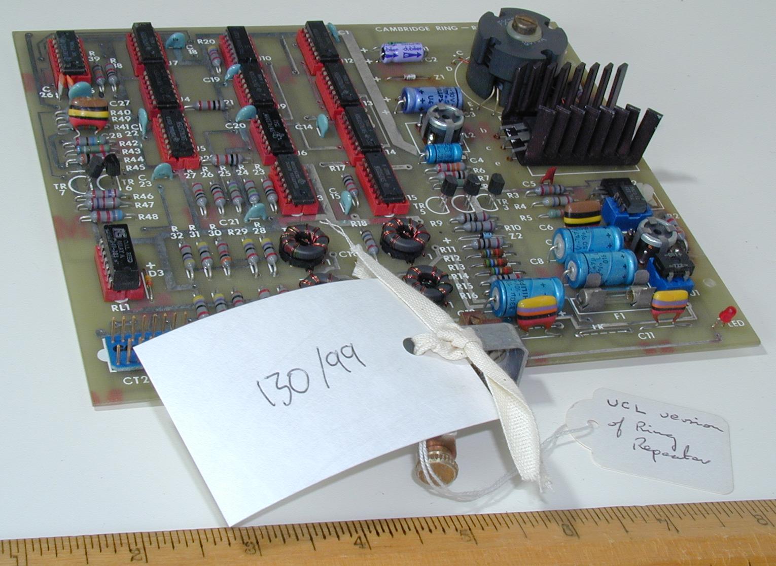
Other No marked on object: none
Inscription: CAMBRIDGE RING - REPEATER (embossed on surface)
Dimensions: 185x170x30
Description: Small printed circuit board. Array of chips, cores and other components. Some evidence of heat damage in places. 15-pin D-type connector on one side.
Class: network
Machine name: Ring
Condition: fair
Notes: One of the Ring manufacturers
Unique id/year of acquisition: CL-131/99
Name: ring station
Other No marked on object: none
Inscription: Station Logic Mk.3 Serial No.06 (sticker on side)
Dimensions: 215x180x65
Description: Metal case with brown plastic sides. One face has a 16 pin plug, one side has two 50 pin plugs.
Class: network
Machine name: Ring
Condition: good
Notes:
Unique id/year of acquisition: CL-132/99
Name: SEEL monitor card
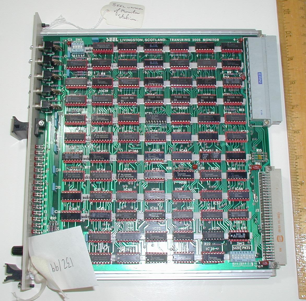
Other No marked on object: none
Inscription: SEEL LIVINGSTONE, SCOTLAND TRANSRING 2005 MONITOR (embossed on top) SERIAL NO 100038(label on front). Hard to read handwritten label on back
Dimensions: 254x245x30
Description: Printed circuit board. Mostly chips (74 series). 64-pin vero connector and an 11-pin ERNI connector on one edge. Case front on other with LEDs, switches, some labels, a knob and two hand-holds. rear is hidden by metal case.
Class: network
Machine name: Ring
Condition: good
Notes: One of the Ring manufacturers
See also: CL-133/99
See also: CL-134/99
Unique id/year of acquisition: CL-133/99
Name: SEEL station card
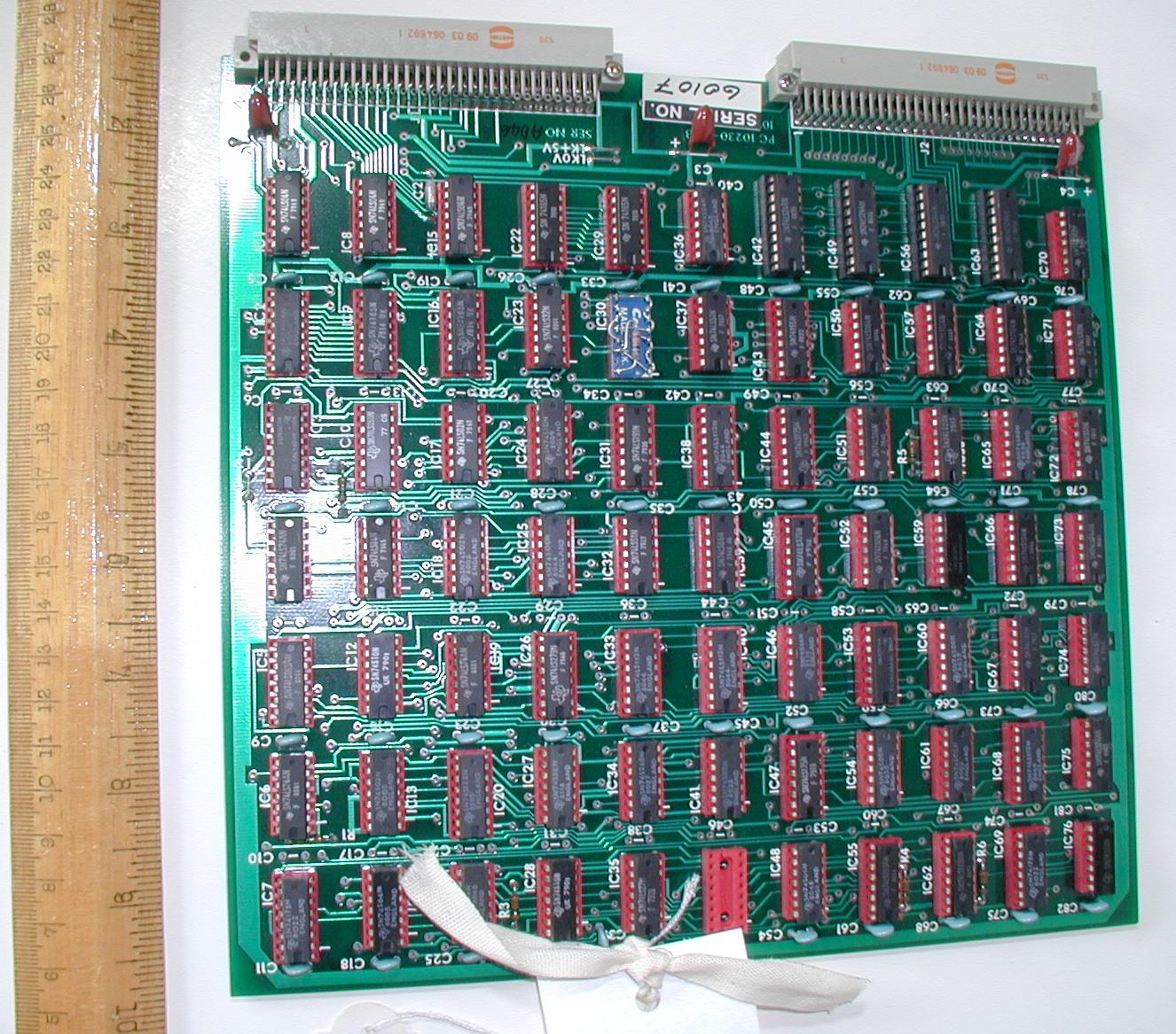
Other No marked on object: none
Inscription: SERIAL NO 60107 (sticker on top)
Dimensions: 232x227x10
Description: Printed circuit board. Mostly chips (74 series). Two 64-pin vero connectors.
Class: network
Machine name: Ring
Condition: good
Notes: One of the Ring manufacturers
See also: CL-132/99
See also: CL-134/99
Unique id/year of acquisition: CL-134/99
Name: SEEL repeater card
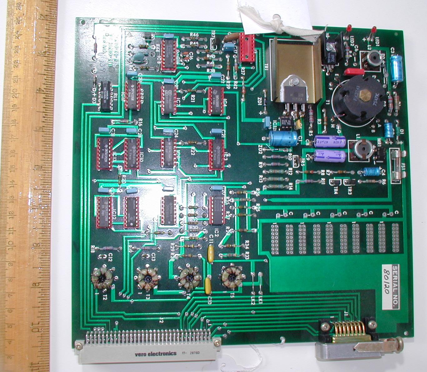
Other No marked on object: none
Inscription: SERIAL No 80/20
Dimensions: 230x230x20
Description: Printed circuit board. Small number of chips, some cores, power transistor, heatsink, fuse and other power components on one half. Two connectors on one edge, one a 15-pin D-type, the other a 64-pin vero.
Class: network
Machine name: Ring
Condition: good
Notes: One of the Ring manufacturers
See also: CL-133/99
See also: CL-133/99
Unique id/year of acquisition: CL-144/00
Name: CFR monitor
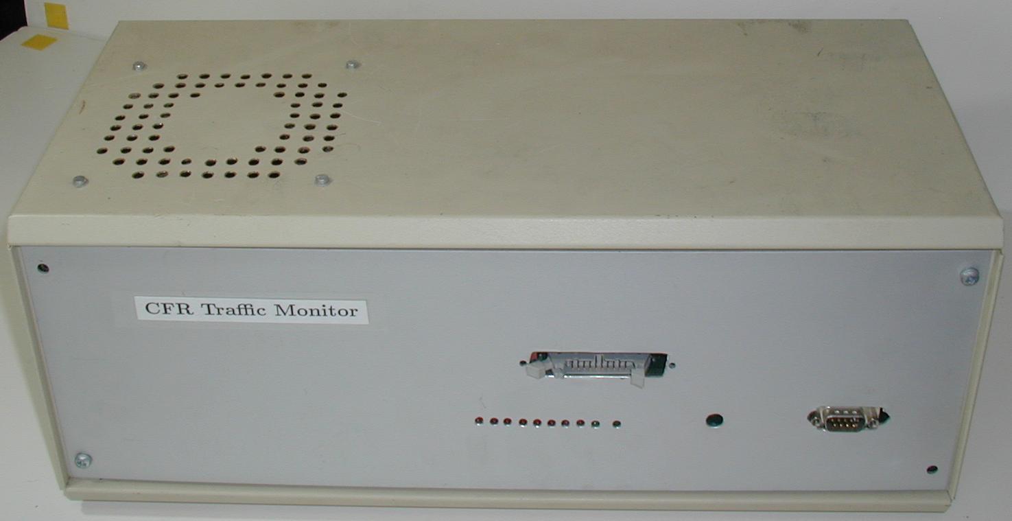
Other No marked on object: none
Inscription: CFR Traffic Monitor (label on front)
Dimensions: 405x195x165
Description: Buff metal case with ventilation holes. Silver front with a line of 8 red and 1 green LEDs, a 20 pin and a 9 pin plug. Brown rear has a power socket, a green on/off switch and a small knob. Rubber feet.
Class: network
Machine name: Ring
Condition: good
Notes:
Unique id/year of acquisition: CL-145/00
Name: Ring terminator
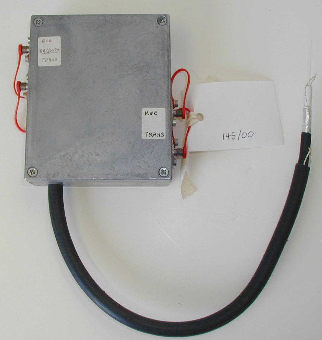
Other No marked on object: none
Inscription: Sapphire (stick on label)
Dimensions: 120x120x35
Description: Grey metal box with fibre optic cable protruding from bottom. Both left and right sides have two fibre optic ports.
Class: network
Machine name: Ring
Condition: good
Notes: Terminator for OMS Ring link (Sapphire = OMS, Emerald = Titan, Ruby = rest of building), probably sat in the Workshop.
Notes
- Identifiers are written on objects in the format CL-uuu/yy/gg (u = unique identifier, y = year of acquisition or entry into database, g = group id. The group id is only used if there are more than one of a given object.) eg 80/99/3. This format was adopted to make the identifiers from this exercise distinct from any used in previous cataloguing attempts.
- Photographs. Where relevant the database contains a comma-separated list of Unix path names of pictures of the object, in jpeg format. If photos are available a thumbnail image will be shown as a search result. Click on this to see the full size image.
- Date format: dd.mm.yy
- Name format: Full first name (where known), else initial and surname
- Dimensions: max x next x min (all in mm)
- Lists in all fields are comma separated.
- n/a = not applicable
blank = no information entered
? = information uncertain or unknown
The database search allowed by this page is selective and will only display information that is present, i.e. it will not display labels for empty fields. - Not all information in the database is displayed on the web page produced by this search facility, some of it is private (eg location of object, for security reasons).
- The Notes section of the database may contain html formatting commands to allow it to be displayed to best advantage on the web pages output by this search facility.