
Course pages 2015–16
ECAD and Architecture Practical Classes
Introduction to Qsys
Raising the abstraction
It is possible to build systems out of handwritten (System)Verilog alone, but it scales poorly. As the number of modules rises, the amount of interconnection between them rises too. It then becomes tedious and error-prone to connect modules by hand, and to manage the necessary requirements (for instance preventing address clashes).
For this reason we tend to use generators, tools written in a higher-level language that generate Verilog suitable for synthesis. Many semiconductor companies to have their own sets of tools written in Perl or Python, or supplied by third-party vendors. In this exercise we'll use Qsys, an Altera GUI tool designed to build hardware systems from libraries of reusable components. As well as instantiating the components, Qsys also constructs a network-on-chip to interconnect them, which can use either unidirectional point-to-point links ('Avalon Streams') or memory-mapped interfaces that have address, data and consist of reads and writes (two formats, 'Avalon Memory-Mapped' and the standard 'AXI').
In this exercise we will implement your rotary controller as a Qsys component, and learn how to plug systems together.
Take a copy of your existing FPGA directory ecad_fpga_1 and call it ecad_fpga_2. Start Quartus and open the project from your new directory. You can then start Qsys from within Quartus II by clicking Tools->Qsys. When loaded with a design, the Qsys window looks something like this:
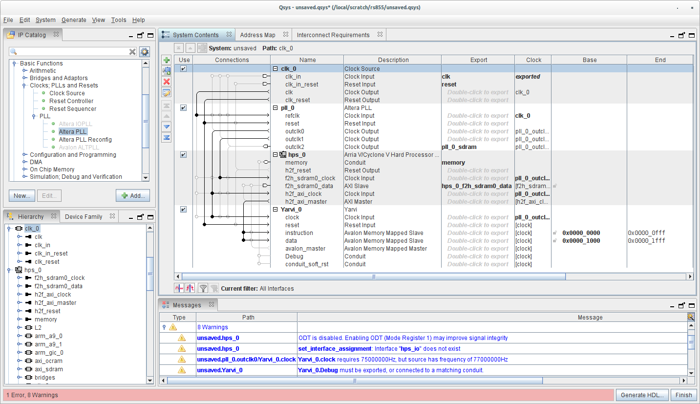
The IP catalog lists the standard components that you can add to your Qsys project. When double-clicking on such a component, it will be added to the System Contents lists. A new window or tab will appear that will let you set various parameters for the chosen component
Generally components have four types of signals: a clock signal, a reset signal, one or more input and one or more output signals. Qsys groups various relevant signals together to maintain overview; for instance if a component has an "Avalon Memory Mapped Slave", all the input and output signals it is comprised off will be grouped into one Avalon slave signal group. By clicking the circles in the connections column, you can then connect signals to compatible sources. Double-clicking in the export column instead lets you export a signal from the project so you can hook them up to other Qsys projects or to your top-level SystemVerilog file.
The Avalon Memory Mapped interface connects multiple slave components to one or more masters. While underneath it is a switched network-on-chip, it provides an abstraction similar to a traditional bus. Differentation between the various components is done by looking at the memory address for any read or write operation on the 'bus'. In the "Base" column you can set an offset within the memory range of the Avalon MM bus. If the offset is not determined by system restrictions, you can use the "Assign base addresses" option in the system menu to have these offsets automatically assigned. Qsys will add additional routing logic required to ensure your components only receives signals when it is addressed by the master.
When a Qsys component is finished, you can press the "Generate HDL" button. Make sure 'create HDL design files for synthesis' is set to Verilog, and click Generate. This will generate all relevant files for use within your Quartus II project: an HDL file for every (sub-)component you instantiated, a project file you can import in your Quartus II project and an overarching Verilog component that you can instantiate in your (top-level) module to import the QSys project into your system.
Building a Qsys component
Create a Qsys project that connects the counter of your rotary encoder controller to the 7-segment displays on the FPGA. To do so, first start Qsys and go to File | New component.... In the "Files" tab, add the rotary encoder and debouncer SystemVerilog files to the Synthesis files. Make sure the Attributes column has rotary.sv as the Top-level File - if not, double click on the rotary's entry and set it as the top level.
Then press "Analyze synthesis files". This will parse your code and identify the signals within. Based on the names it will then make a guess at their types (sometimes incorrectly). If you get lots of errors at this stage, it probably guessed wrong so we next have to set the types and grouping of signals. Before that, check that the Top-level Module is correct for your rotary encoder.
By grouping signals into interfaces, we enforce a degree of type checking: for instance Qsys will complain if we have a memory bus without an address, or an interface without a reset.
Go to View | Signals. This will display the signals it found, and attempt to group them into interfaces. For the rotary encoder we'll be creating a number of interfaces:
| Interface name | Interface type |
|---|---|
| clock | Clock input |
| reset | Reset input |
| rotary_in | Conduit, a variably-sized bundle of unstructured wires (2 bits here) |
| rotary_pos | Conduit (8 bits) |
| rotary_event | Conduit (2 bits) |
We'll put rot_cw and rot_ccw into the rotary_event conduit.
Work down the Interface column creating interfaces as you need (for instance New Conduit....) Do not worry about names at this stage. The aim is to group the signals together appropriately and set their types.
Next, work down the Signal Type column setting the types of signals within individual interfaces. For instance, we're declaring a Conduit called rotary_event that contains two wires, one called rotary_cw and another called rotary_ccw. Applying types here prevents these wires getting accidentally mixed up when we connect them to a consumer. We'll call the type of the counter output export and match this with the type of the input we'll connect it to.
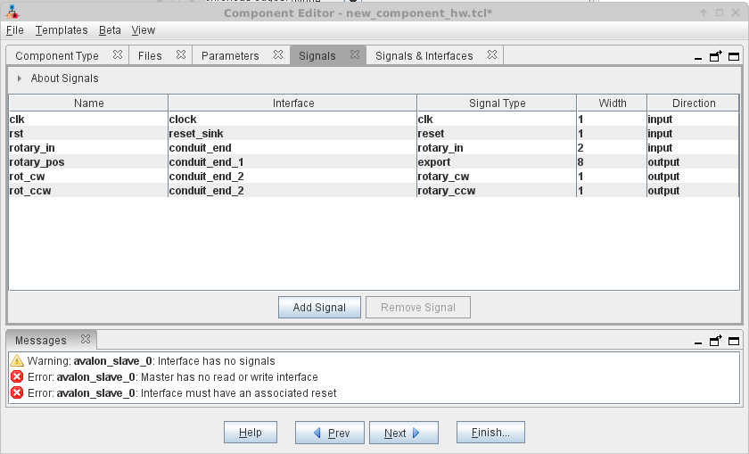
Now flip to the Signals & Interfaces tab. Here you should see the signals correctly grouped. If there are extra empty groups (for instance avalon_slave_0) you will need to delete them by right-clicking. You can now click on a group to rename it, and set up any more parameters necessary -- for instance, many interfaces will require assigning an associated reset. In the case of export we want to leave it without a clock/reset.
The result should look like this:
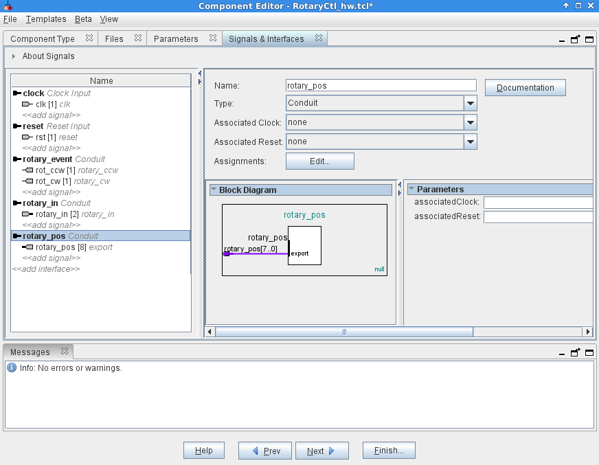
Please make sure that all names and signal types correspond. It is important that rotary_pos does not have an associated clock and reset, to match the type of the places we will connect it to.
Finally go to the Component Type tab and call your component RotaryCtrl in both Name and Display Name. Finish... to save your component.
Joining components into systems
Download 7seg.zip and unpack the files to the same level as your Quartus project. We have provided a Qsys component called EightBitsToSevenSeg which very simply takes an 8 bit input and produces two hex digits for display on the LEDs.
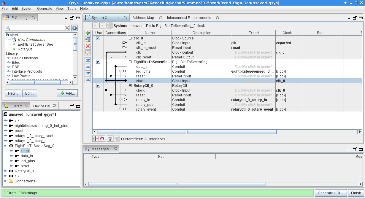
In Qsys, go to File | New system. You should see EightBitsToSevenSeg and RotaryCtl in your IP Catalog to the top left, if not press F5 or do File | Refresh System to update.
Double click EightBitsToSevenSeg and RotaryCtl in turn to add one to your project. For each you will be shown a block diagram and be given an opportunity to set parameters for your component. Since we didn't add any parameters there is nothing to set, so click Finish to add.
We now have a system with a Clock Source, an EightBitsToSevenSeg and a Rotary Ctl.
First, let's connect up the clock. See there is a greyed out line between the Clock Output of clk_0 and the Clock Input of RotaryCtl_0. Click the circle on it, which will make the connection. This is now a type-checked connection, and Qsys is aware of the properties of clocks: for instance it knows that RotaryCtl is now on the clock domain belonging to clk_0. Similarly, click on the circle for the clock input of EightBitsToSevenSeg to join that to clk_0.
Do the same for the reset.
Next, we have some pins that we want to connect outside the Qsys system, for which we use the Export column. Where it says 'Double click to export', double click on the rows corresponding to led_pins, rotary_in and rotary_event. The default names are fine. These signals will now appear as interfaces to the top level of the Verilog hierarchy when we generate the system.
Finally, we want to connect the rotary_pos (the count of the rotary position) to the LED data input. Click on the circle next to data_in and then circle next to rotary_pos to join them together. Since they are both of type export Qsys should accept the types are consistent.
The finished system should look like this:
Generating Verilog
If you are happy with the system and Qsys reports no errors, save your Qsys file as rotary_hex. Then click the Generate HDL... button to generate Verilog (the default options are fine).
This will make a rotary_hex/synthesis/rotary_hex.qip file that references the intellectual property (IP) that Qsys has created. You need to add the .qip (but not the .qsys) to your Quartus project to build it into your FPGA.
Additionally, we need to instantiate the Qsys system in our toplevel Verilog. In Qsys, go to Generate | HDL Example.... This provides some HDL you should copy and paste into your Verilog file. You will need to fill in the signals in brackets:
Connect the clock to CLOCK_50 and reset_n to KEY[0].
Connect led0 to HEX0 and led1 to HEX1.
Connect rotary_in to DIALL.
Comment out the lines referring to rotary_event, since we don't use them here.
You should now be able to synthesise your FPGA and test your Qsys system.
Exercise 5
To the same Qsys project, add some more instances of the RotaryCtl and EightBitsToSevenSeg to drive the right-hand rotary encoder. Connect them to the HEX2 and HEX3 LEDs. Verify that your set-up works correctly.
Optional exercise
Extend your Qsys project to also include the shift register. Assign all the shiftreg_ pins to a conduit named shiftreg_port (make up some type names for each pin) and the buttons pins to a conduit named how you like but of type export, in both cases without associated clock or reset. Export its signals and connect them to the ten LEDs on the FPGA.