
Course pages 2015–16
ECAD and Architecture Practical Classes
Exercise 6: Etch-a-sketch (or Pong) on FPGA
Adding your Verilog components
Now is time to add your rotary controllers and shift register to your Qsys project, so we can access them from Yarvi.
From Exercise 5, copy the Verilog for the rotary encoders and shift register into your yarvi_fpga folder. Also copy the files ending _hw.tcl - these are the defintions for your Qsys components.
Start Qsys and open yarvi_soc.qsys. If you have Qsys already open, go to File | Refresh System (or press F5) to cause Qsys to rescan and add them to its library of components.
In Qsys you should see the rotary encoder (and shift register if you made a Qsys component) appear as components in the IP Catalog on the left. You can double click to add one instance to your design. Add a rotary controller.
Next we'll wire them up to PIOs to make them accessible to the Yarvi. In the IP Catalog, find Library -> Processors and Peripherals -> Peripherals -> PIO (Parallel I/O) (you can also use the search box). Double click to add one.
Set this first PIO to be 8 bits wide and an input. Leave the rest of the settings at their defaults and Finish the PIO dialogue, and find the PIO entry you just created at the bottom of the Qsys System Contents. Right click and rename it to pio_left.
Connect the clock and reset of RotaryCtl_0 and pio_left to the clock and reset used on the Yarvi. Connect the memory slave of pio_left to the Avalon Master of the Yarvi. Export the rotary_in and rotary_event ports of the rotary controller. Finally join the rotary_pos output port of the rotary controller to the external_connection of the PIO.
Add a second rotary controller and connect it to another PIO, 8 bits wide and an input, called pio_right.
If you made a shift register Qsys component, add it and connect it to a third PIO called pio_buttons that is 16 bits wide and an input.
If you did not do that, make the PIO anyway and export the external_connection. You'll have to instantiate your shift register in your toplevel Verilog file and wire it to the clock, reset and exported connection from the PIO.
Finally we need to assign base addresses for the peripherals we've just added, to match the definitions in avalon_addr.h:
| Component | Base address |
|---|---|
| pio_left | 0x04000100 |
| pio_right | 0x04000200 |
| pio_buttons | 0x04000300 |
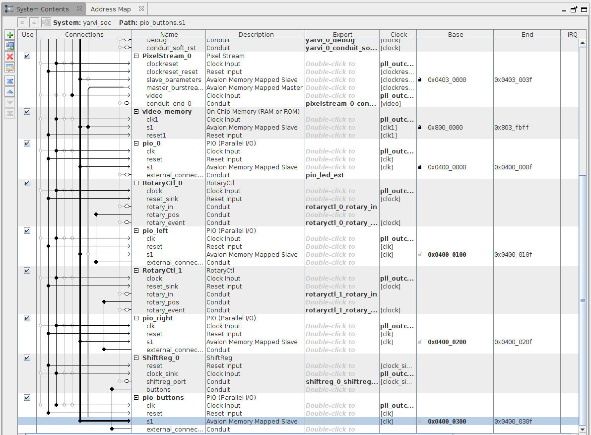
Your system should like similar to the image below (if you had the shift register in Qsys):
If you didn't, the bottom part will look like:

We have now finished adding hardware to the system so we can generate the system. Before doing so, go to Generate | HDL Example and copy the code to instantiate the Qsys project in your top level Verilog. Then you can Generate HDL...
While it is generating, go back to Quartus and open toplevel.sv. Using the code you copied, adjust the instantiation of the Qsys project to add any extra ports that are now present on the Qsys project (it is probably safer to cut and paste ports into the existing declaration than paste in a complete new declaration from scratch - making an error with the memory or reset connections can be time consuming to debug).
If you didn't have a shift register Qsys component and instead exported the PIO pins to the top level, now is the time to make an instantiation of the shift register controller and wire buttons into the pio_buttons that were exported from Qsys.
Wire the ports from the Qsys instantiation as follows (your names may be slightly different):
| Qsys port | I/O pin |
|---|---|
| rotaryctl_0_rotary_in_rotary_in | DIALL |
| rotaryctl_0_rotary_event_cw | Don't connect |
| rotaryctl_0_rotary_event_ccw | Don't connect |
| rotaryctl_1_rotary_in_rotary_in | DIALR |
| rotaryctl_1_rotary_event_cw | Don't connect |
| rotaryctl_1_rotary_event_ccw | Don't connect |
| shiftreg_0_shiftreg_port_shiftreg_loadn | SHIFT_LOAD |
| shiftreg_0_shiftreg_port_shiftreg_out | SHIFT_OUT |
| shiftreg_0_shiftreg_port_shiftreg_clk | SHIFT_CLKIN |
Adding your software and building the FPGA
From your simulation project, copy in your Etch A Sketch or Pong code into yarvi_fpga/yarvi/software. Take care not to replace avalon_addr.h which has changed from the simulation version. Add any more files you need to the Makefile. Change to this directory in your terminal and type 'make' to build your software.
Once your software builds correctly, now is the time to start your FPGA synthesis. While it is building, have a look at the questions for Tick 2.
When your build has completed, download to your FPGA and test your code.