
Raspberry Pi
Section 2: GPIO
Let's start with an introduction to using the Raspberry Pi's General Purpose Input Output (GPIO) facilities.
Operating a Simple Switch and LED on the Raspberry Pi
GPIO, as may have been explained in other tutorials, stands for General Purpose Input/Output and a GPIO pin can be set high (taking the value 1) by connecting it to a voltage supply, or set low (taking the value 0) by connecting it to ground. The Raspberry Pi can set the pin to take either value and treat it as an output, or it can detect the value of the pin and treat it as an input.
The Raspberry Pi's pin header looks like this:
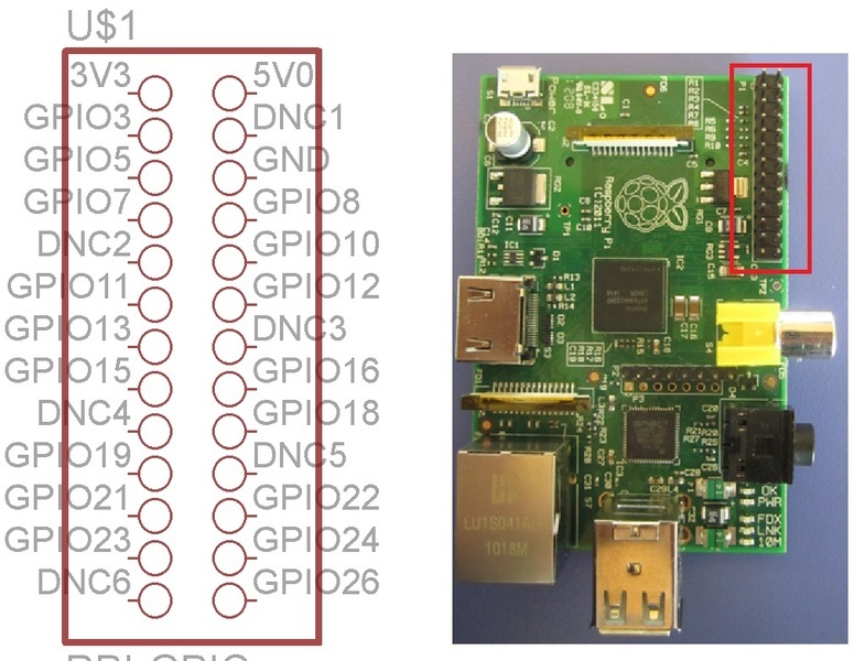
There are twenty-six pins in total: three power supply pins, 3V3 (3.3V), 5V0 (5.0V) and GND (0V); 6 DNC (do not connect) pins; and seventeen GPIO pins. Some of these seventeen pins have alternative functions as well, but we won't dwell on those now.
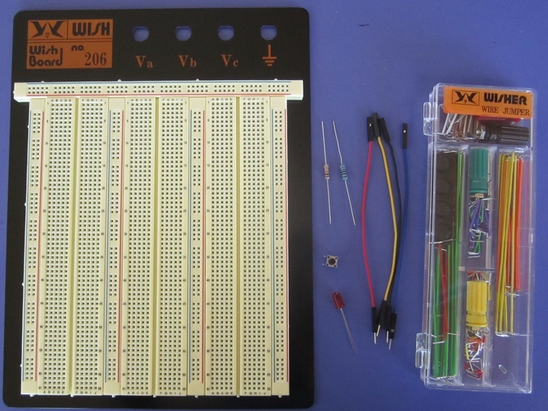
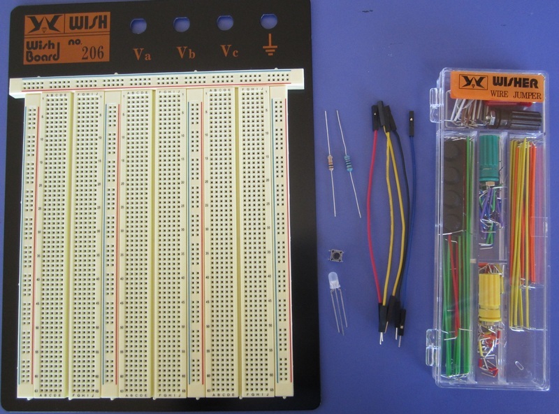
Let's build a simple circuit with a switch and LED. You will
need:
– 1 × Working Raspberry Pi with an Internet
connection
– 1 ×
Breadboard + jumpers
– 4 ×
Male/female jumper cables
– 1 ×
LED
– 1 ×
Pushbutton switch
– 1 ×
270Ω resistor
– 1 ×
10kΩ resistor
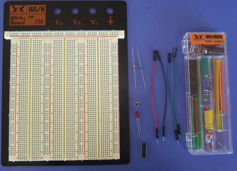
A breadboard has several key features. It has red and blue lines which demarcate the holes belonging to the supply voltage rails (which will be 3.3V for our purposes since the GPIO pins operate at 3.3V) and ground rails (GND) respectively. The holes in the same group are linked via connections inside the breadboard.
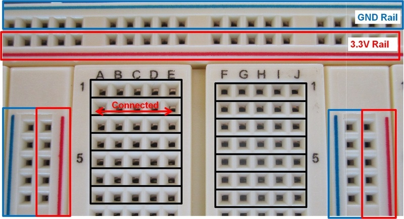
The rest of the pin holes can be grouped into segments of 5 shown in the black boxes. The holes in each segment are linked together, but the segments are not connected to one another.
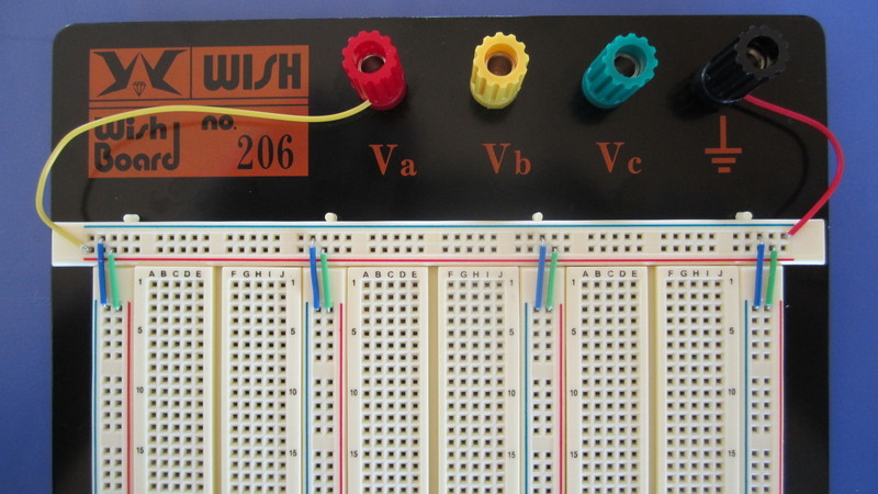
It is recommended to link up all the supply voltage and ground rails as shown below for easy wiring later on.
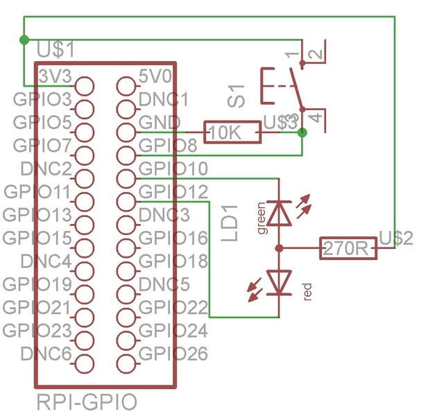
The circuit diagram for the LED switch is:
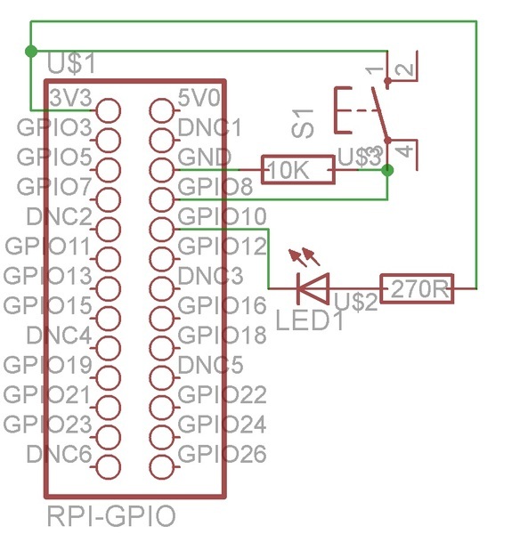
GPIO10 is used as an output. When it is set low, the LED will be turned on, and vice-versa when it is set high. GPIO8 is used as an input, so when the pushbutton switch is pressed the pin is set high.
So, what can we actually do? Lots!
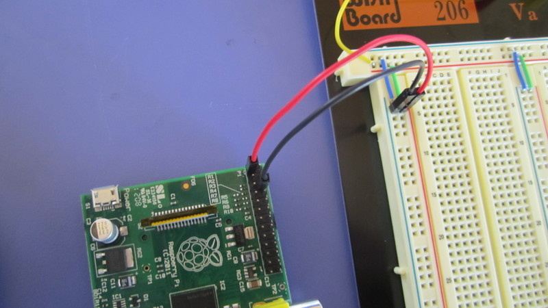
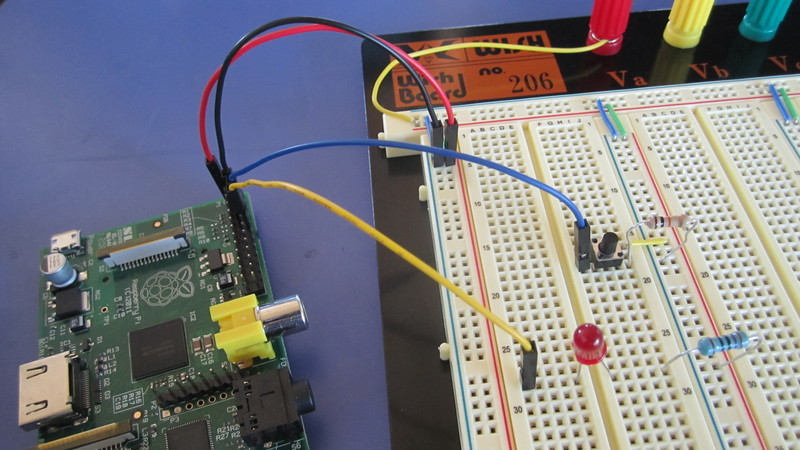
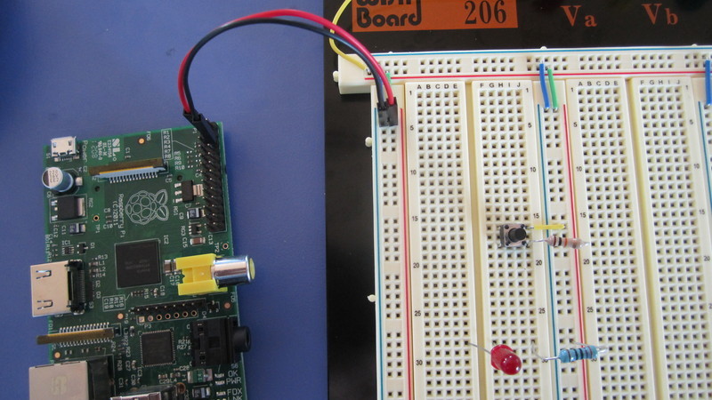
Connect the 3.3V and GND pins of the Raspberry Pi to the corresponding rails on the breadboard using the male/female jumper cables.
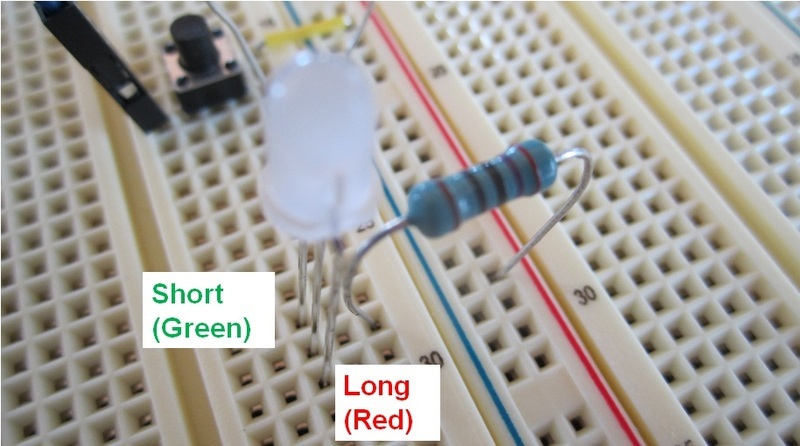
Connect the LED along with the 270Ω resistor and wire them to the 3.3V rail according to the circuit diagram. You will need to refer to the technical datasheet (this is only for the specific LED used in this tutorial) to determine which pin should be connected to the voltage supply (positive rail) and which should be connected to the pin (negative). From the datasheet, the shorter pin is labelled ‘anode’ and should be connected to the positive rail. The datasheets are usually found on the product page for electronic components.

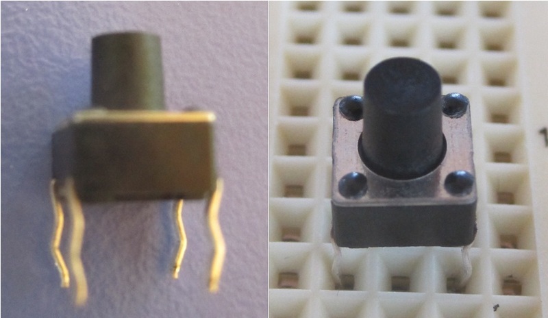
Add in the switch and the 10kΩ resistor. Note that the pushbutton switch has 4 pins and you will have to decide which two pins to connect to the pin header by referring to its technical datasheet. The pins 1 to 4 according to the datasheet are connected as shown below.
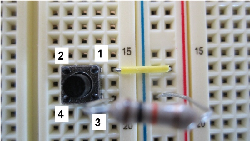
If you find that the switch doesn’t fit into the breadboard well, straighten the pins using a pair of pliers a little before inserting it into the board.
Now, connect the LED to GPIO10 pin of the Raspberry Pi pin header and the switch to GPIO8 pin.
Now, we'll write some code in Python to trigger the turning on of the LED upon pressing the switch. First, we need to install a Python module, RPi.GPIO, to control the GPIO pins for the Raspberry Pi.
Type the following lines in LXTerminal to do so:
sudo apt-get install python-rpi.gpio
Now, open a text editor and type the following code. This will
program the switch and LED, and the LED will be turned on when
the switch is pressed. To run the code, type python your_filename.py in a
terminal.
# Import the required module.
import RPi.GPIO as GPIO
# Set the mode of numbering the pins.
GPIO.setmode(GPIO.BOARD)
# GPIO pin 10 is the output.
GPIO.setup(10, GPIO.OUT)
GPIO pin 8 is the input.
GPIO.setup(8, GPIO.IN)
# Initialise GPIO10 to high (true) so that the
LED is off.
GPIO.output(10, True)
while 1:
if GPIO.input(8):
GPIO.output(
10, False)
else:
# When the button
switch is not pressed, turn off the LED.
GPIO.output(
10, True)
Operating a bicoloured LED on the Raspberry Pi
Next we'll replace the normal LED with a bicoloured LED. You
will need:
– 1 × Working Raspberry Pi with an Internet
connection
– 1 ×
Breadboard + jumpers
– 5 ×
Male/female jumper cables
– 1 ×
Bicoloured LED
– 1 ×
Pushbutton switch
– 1 ×
270Ω resistor
– 1 ×
10kΩ resistor
The circuit diagram for the bicoloured LED pins is:
GPIO10 controls the green LED, GPIO12 controls the red LED, and the switch remains the same.
- Swap the LED in the previous circuit with a bicoloured LED
in the following manner. For the bicoloured LED, we need to
check the technical
datasheet to determine how to connect the pins. In this
case, the central pin is the anode pin and should be connected
to the power rail via a resistor. The remaining longer pin
corresponds to the red LED and should be connected to GPIO12
(bottom) while the last shorter pin should be connected to GPIO10
(top).
- Connect the LED pins to the GPIO pins on the Raspberry Pi
pin header using two jumper cables.
Now, let's have code that changes the state of the LED every second when the button is pressed:
# Import the required modules.
import RPi.GPIO as GPIO
import time
# Set the numbering sequence of the pins, then
set pins ten and twelve to output, and pin eight to
input.
GPIO.setmode(GPIO.BOARD)
GPIO.setup(10, GPIO.OUT)
GPIO.setup(12, GPIO.OUT)
GPIO.setup(8, GPIO.IN)
# Turn both of the LEDs off.
GPIO.output(10, True)
GPIO.output(12, True)
# The SwitchState variable is 1 if the button
is pressed, and 0 otherwise. LEDState is 0 when off, 1 when
red, and 2 when green.
SwitchState = 0
LEDState = 0
while 1:
if GPIO.input(8)
# When the LED is off, keep the green LED off,
turn the red one on, then change the state of the LED to
reflect that it is red, and wait one second.
if LEDState
== 0
GPIO.output(10, True)
GPIO.output(12, False)
LEDState = 1
time.sleep(1)
# When the LED is red, turn the green LED on,
turn the red one off, then change the state of the LED to
reflect that it is green, and wait one second.
elif
LEDState == 1
GPIO.output(10, False)
GPIO.output(12, True)
LEDState = 2
time.sleep(1)
# When the LED is green, turn it off, then
turn the red one off, then change the state of the LED to
reflect that they are all off, and wait one second.
elif
LEDState == 2
GPIO.output(10, True)
GPIO.output(12, True)
LEDState = 0
time.sleep(1)
Expanding the Raspberry Pi pin header.
This section will explore how to increase the number of I/O pins available in the scenario where we want to use a lot more switches and LEDs in large projects. To do so, we will use the PCF8574AN chip, which is an 8-bit I²C Bus I/O expander.
The I²C Bus is a network which contains a master (Raspberry Pi) and a slave (PCF8574AN). The two communicate via a data line (SDA) and clock line (SCL). The slave also has an address so that the master can identify it on the network, which usually has multiple slave devices.
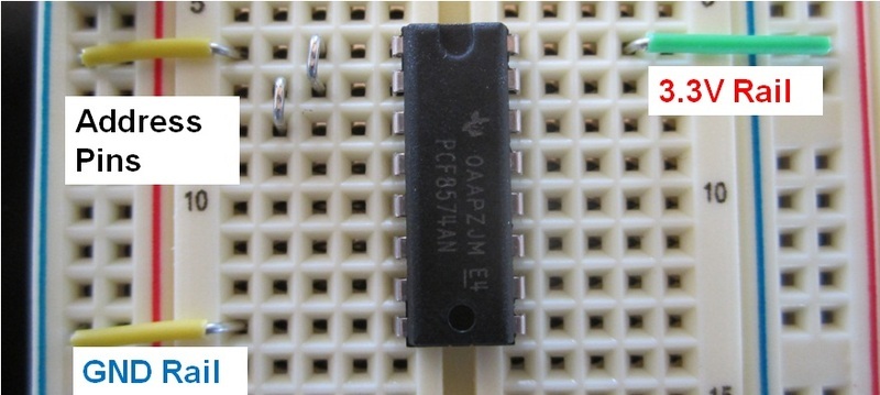
Let's explore the pins of the PCF8574AN and revisit the pins of the Raspberry Pi pin header. The top of the PCF8574AN is denoted by a groove as shown in the datasheet.
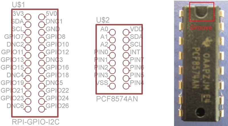
Both headers have SDA and SCL pins which are to be connected to one another to form the data and clock lines. As mentioned previously, some of the Raspberry Pi pins have multiple functions. GPIO3 and GPIO5 are 2 of them and they act as SDA and SCL pins for I²C Buses as well.
The pins A0, A1, and A2 are address line pins which form the last three bits of the device address.
There are also 8 I/O pins, and to set or detect the values of these pins, we have to write or read 8 bits of data using the data line. Each bit will correspond to one of the values of the pins. For example, if we have 8 LEDs connected to all 8 pins on the I/O expander, and we only want to turn on the LED connected to pin 0, we write the data "01111111" to the I/O expander. (Assuming that the LED is connected between the voltage supply and the pin, it is turned on only when the pin is set to 0.)
To demonstrate the usage of the I²C Bus network we shall alter
our previous circuit such that the LED and switch are connected
to the pins of the I/O expander rather than the Raspberry Pi
pin header directly. You will need:
– 1 × Working Raspberry Pi with an Internet
connection
– 1 ×
Breadboard + jumpers
– 4 ×
Male/female jumper cables
– 1 ×
Bicoloured LED
– 1 ×
Pushbutton switch
– 1 ×
270Ω resistor
– 1 ×
10kΩ resistor
– 1 ×
PCF8574AN I/O Expander.
The circuit board looks like:
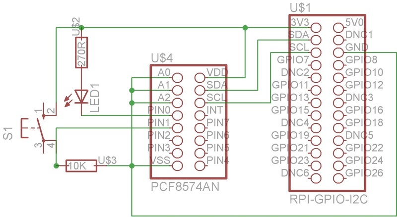
The address pins are all set low, so the last 3 bits of the I/O expander's address are 000. To find out what the full address is, we'll have to refer to the technical datasheet for the chip. There is an address reference table which displays the various addresses in decimal or hexadecimal for every combination of the address pins. For the case when all address pins are set low, the address is 56 in decimal. There is also a section detailing the first 4 bits of the address which are 0111. With that, the 7-bit binary address is 0111000 which is equivalent to 56 in decimal.
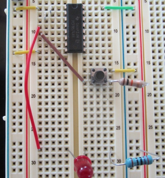
The switch is now connected to Pin 1 of the I/O expander and the LED is controlled via pin 0.
- Connect the circuit according to section 1, but remove the
male/female jumper cables connected to the switch and LED.
- Insert the I/O expander and connect the Vdd and Vss pins of
the I/O expander to the 3.3V and GND rails respectively.
Then, connect all of the address pins to the GND rail.
- Connect the LED to Pin 0 of the I/O expander and the switch
to Pin 1.
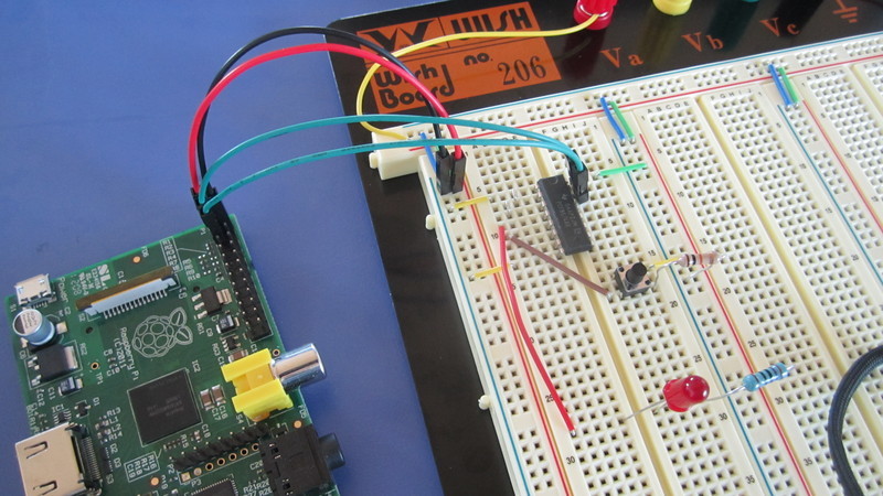
- Finally, connect the SDA and SCL pins of the I/O expander
to those on the Raspberry Pi pin header using male/female
jumper cables.
To use the I²C adapter with the Raspberry Pi, install and enable the required drivers and packages:
- Enable the I²C driver on the Pi by typing sudo nano /etc/modprobe.d/raspi-blacklist.conf and commenting out (adding a # sign to the beginning of the line beginning) 'blacklist i2c-bcm2708', then exit the editor (Ctrl+X, y to save, Enter).
- Edit the modules file with the command sudo nano /etc/modules and add "i2c-dev" to a new line, then save the file as before.
- Update all of the packages installed on the Pi by typing sudo apt-get update. This could take several minutes.
- Install the i2c-tools package: sudo apt-get install i2c-tools.
- Add a new user to the i2c group: sudo adduser pi i2c.
- sudo shutdown -r now (reboot) the machine
- After the reboot, test to see if there is a device connected with the command i2cdetect -y 0.
- Install the python 'smbus' module: sudo apt-get install python-smbus.
Activate the I²C device with sudo modprobe i2c-dev. This must be done whenever the Pi is restarted.
Now for some code to turn the LED on and off when the pins are
plugged into the I²C:
import smbus
# Access the i2c bus now.
bus = smbus.SMBus(0)
# Now write 1 to the device with the address
56, turn off the LED by setting pin 0 to 1, and reset the
switch by switching pin 1 to 0.
bus.write_byte(56, 1)
while 1:
# If the button is pressed, pin 1 will be 1 and
the byte read from the device with address 56 will be
00000010 (2) or 0000000011 (3).
if bus.read_byte(56) in
(2,3):
# Write 00000000, setting pin 0 to 0, turning
on the LED, and resetting the switch with pin 1 to 0.
bus.write_byte(56, 0)
else:
# Write 00000010, setting pin 0 to 1, turning
off the LED, and pin 1 to 0 to reset the switch.
bus.write_byte(56, 1)
Now you have a basic grounding in components, breadboards and electronics, it's time to build a Turing machine!