
Course pages 2019–20
ECAD and Architecture Practical Classes
Optional Exercise A*: Tone generator
Scheduling
If you finish Exercise 2 before the end of week 3 you can attempt this exercise. You should proceed to Exercise 3 if it is week 4 or later.
Outline
The DE1-SoC has an audio CODEC (enCOder / DECoder) chip onboard with microphone input, line in, and line out. The CODEC contains a Digital-to-Analog Converter (DAC) which generates an analog audio signal from digital audio samples fed into it.
Altera provide 3 pieces of IP with the University Program which we'll use to configure and drive the CODEC:
- Audio and Video Config: configures the CODEC over an I2C bus with parameters specified in Qsys.
- Audio Clock for DE-series Boards: a PLL which generates the 12.288MHz clock for the CODEC.
- Audio: Provides a FIFO buffer for audio samples, and feeds them serially to the CODEC.
We'll configure the CODEC to accept left-justified 16-bit samples at a rate of 48kHz.
Altera's Audio IP provides either an Avalon-MM or Avalon-Streaming interconnect for use in Qsys. We'll use the Avalon-Streaming interface and export it from Qsys, which lets us access the FIFOs directly from our toplevel.
The Avalon-Streaming interface is used for point-to-point data transfer between sources and sinks. When there is space in the sink's FIFO to receive new data, the sink asserts the ready signal. When the source has data ready to send, it asserts the data on the data signal, and asserts the valid signal. Once the FIFO is full, the sink deasserts the ready signal. We'll use this simple interface to generate and provide samples to the output FIFOs only when they request more data.
Exercise
Write a Verilog module which generates varying tones from the CODEC.
Your code should have the following module interface:
	module tonegen (
		input clk,
		input reset,
		input logic [7:0] volume,
		input logic [3:0] note,
		input logic [2:0] octave,
		input left_chan_ready,
		input right_chan_ready,
		output logic [15:0] sample_data,
		output logic sample_valid
	);

		/* your code goes here */

	endmodule
Part 1 - Square wave generation
Write some Verilog to produce a square wave with a frequency as close as possible to 130.8 Hz (note C3). The easiest way to do this is with a clock divider.
The amplitude of the square wave should be set by the volume input to your module, and it should be centred around zero - that is, the wave should oscillate from +volume to -volume and back again.
Use ModelSim to verify the output frequency and amplitude.
Part 2 - Qsys Setup
Make a copy of your Quartus project and Qsys system from exercise 2b and make a new Qsys project inside: add the following IP using the IP Catalog on the left (use the search box to find them more easily). Leave each with the default name, and set the parameters according to this list:
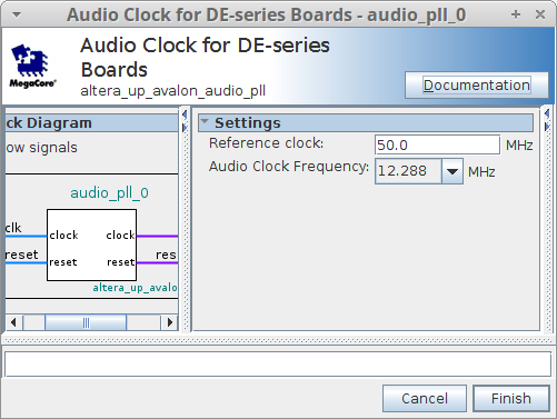
- Audio Clock for DE-series Boards
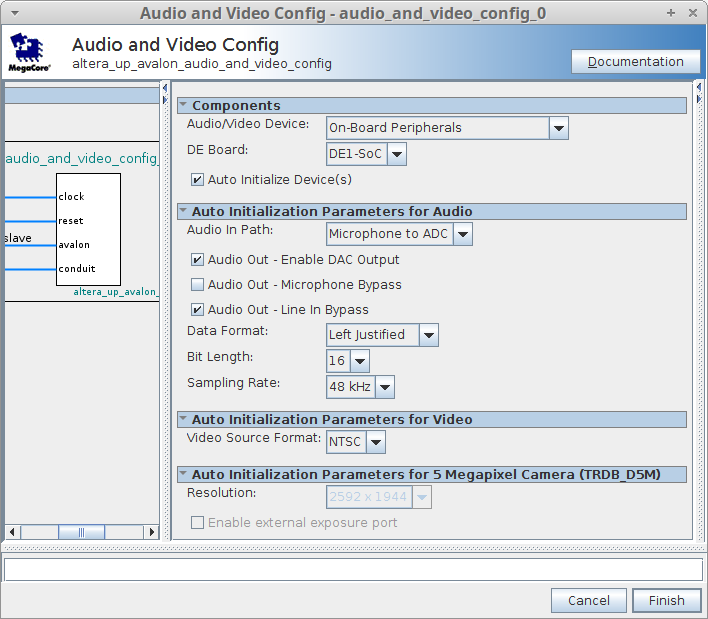
Set Reference Clock to 50.0MHz, and Audio Clock Frequency to 12.288MHz. - Audio and Video Config
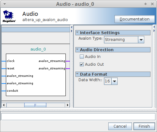
Choose On-Board Peripherals as the Audio/Video Device. Choose DE1-SoC as the board. Check Auto Initialise Device(s). Check Audio Out - Line In Bypass. Change Bit Length to 16. - Audio
Set Avalon Type to Streaming. Uncheck Audio In. Set Data Width to 16.
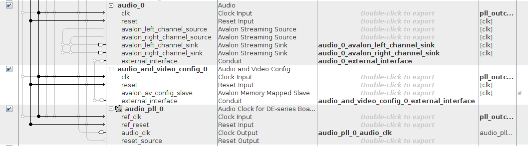
Connect the clock and reset signals of all 3 IP components to the system clock and reset. Export audio_clk from the Audio Clock for DE-series Boards, external_interface from the Audio and Video Config, and external_interface, avalon_left_channel_sink and avalon_right_channel_sink from the Audio.
See the images on the right for a summary of these settings and connections.
Part 3 - Driving the FIFOs
The CODEC removes data from the FIFOs at 48kHz, so we will have to generate samples at this rate. However, we can't guarantee that the FIFOs will ask for data at precise intervals (for example when they start empty, they will ask for 128 samples in rapid succession). For this reason, we want to use the FIFO's ready signal to decide when to run our clock divider to generate samples.
We'll generate a mono audio signal (left and right channels will be fed the same data), so we only want to generate a sample when both the left and right FIFOs have at least one space free.
Modify your verilog code to only run the clock divider when both left_chan_ready and right_chan_ready are high. You'll also need to recompute the cutoff of the clock divider so it assumes a clock frequency of 48kHz rather than 50MHz.
You'll also have to assert the sample_valid output when there is data ready to be stored in the FIFOs.
Download our Verilog testbench for the audio FIFOs and use it to test your implementation in ModelSim. After the initial filling of the FIFOs, you should see samples being generated at a rate of approximately 48kHz. You might have to modify your implementation to make sure it only generates a single sample each time, and that the output has the correct frequency.
The output signals are left_out and right_out in tb_audio_fifos.sv. They represent the signal being sent to the speakers, so should show square waves with the correct frequency.
Note that you might need to run the simulation for a long time to see any change on the output, since you're looking for a signal with a period of around 7.6ms (assuming you're generating the 130.8Hz signal from Part 1).
Part 4 - Generating musical notes
We want to generate a square wave which oscillates at the frequency of the note we select. The frequency of some musical notes is shown in this table:
| Note | Frequency (Hz) |
|---|---|
| C0 | 16.35 |
| C#0/Db0 | 17.32 |
| D0 | 18.35 |
| D#0/Eb0 | 19.45 |
| E0 | 20.60 |
| F0 | 21.83 |
| F#0/Gb0 | 23.12 |
| G0 | 24.50 |
| G#0/Ab0 | 25.96 |
| A0 | 27.50 |
| A#0/Bb0 | 29.14 |
| B0 | 30.87 |
Notes in higher octaves can be obtained by doubling the frequency of the same note in the octave below, e.g. C1 has frequency 32.70Hz.
Rather than compute the frequency each time we choose a new note, we can pre-compute the clock divider cutoff for each of the notes in octave 0 (in the table above). To get higher octaves, we shift the divider value right by the number of the octave we want.
We can declare an array in SystemVerilog as follows: (note the apostrophe before the opening curly brace)
logic [11:0] notes [12] = '{
	0,
	1,
	2,
	3,
	4,
	5,
	6,
	7,
	8,
	9,
	10,
	11
};
We can then use the note input to our module to select a value from this table, and shift it right by the octave input to calculate the cutoff value for our clock divider.
Assuming a base clock frequency of 48kHz, calculate the clock divider values for each of the notes in the table above, and store them in a table like the one shown. Modify your Verilog to use the note and octave inputs to select which frequency of tone to generate.
Use ModelSim to Verify the output frequency of some notes.
Part 5 - Audio output
Save and Generate your Qsys system if you haven't already. Copy the template from Generate | Show Instantiaion Template... to see how to connect the signals we exported.
Instantiate your tonegen, and create some logic signals to connect it to the exported signals from Qsys. Paste in the template and connect it as shown below:
logic [3:0] note;
logic [2:0] octave;
logic [7:0] volume;
logic rdy_left;
logic rdy_right;
logic [15:0] sample;
logic sample_valid;

always_comb begin
	note = 0;
	octave = 3;
	volume = 255;
end

tonegen tg(.clk(CLOCK_50), .reset(~KEY[0]), .volume(volume), .note(note), .octave(octave), .left_chan_ready(rdy_left),
    .right_chan_ready(rdy_right), .sample_data(sample), .sample_valid(sample_valid));

my_audio_system qsys0 (
    .audio_0_avalon_left_channel_sink_data            (sample),
    .audio_0_avalon_left_channel_sink_valid           (sample_valid),
    .audio_0_avalon_left_channel_sink_ready           (rdy_left),
    .audio_0_avalon_right_channel_sink_data           (sample),
    .audio_0_avalon_right_channel_sink_valid          (sample_valid),
    .audio_0_avalon_right_channel_sink_ready          (rdy_right),
    .audio_0_external_interface_BCLK                  (AUD_BCLK),
    .audio_0_external_interface_DACDAT                (AUD_DACDAT),
    .audio_0_external_interface_DACLRCK               (AUD_DACLRCK),
    .audio_pll_0_audio_clk_clk                        (AUD_XCK),
    .audio_and_video_config_0_external_interface_SDAT (FPGA_I2C_SDAT),
    .audio_and_video_config_0_external_interface_SCLK (FPGA_I2C_SCLK)

    ... more connections ...

);
(don't forget that the Qsys system expects an active low reset)
Synthesise your design and upload it to the FPGA.
You can plug a pair of headphones into the line-out (light green) audio connector on the DE1-SoC board to hear the output from the CODEC. Be aware that the volume may be quite loud.
Part 6 - Choosing the note
Modify your Qsys system to export rotary_pos from both left and right RotaryCtl's. You'll have to disconnect them from the hex displays, since you can't both export and internally connect a signal in Qsys. In your toplevel, connect these to the volume and note signals. You may want to use the slide switches (SW) to choose an octave.
Now you can change the volume and pitch of your tone generator while it's running!
Debugging
If your audio generator works in simulation but not in hardware, you might wish to look at the Additional Material for the tutorial for using SignalTap as an on-FPGA logic analyser.