|
Here you are going to create an 8-bit up-down counter module that will later be wired up to control the position of a bat on the
screen. Initially, create a new folder for this stage of the project. It is a good idea to do this for each stage, so you have a
record of how the project progressed through each stage. Into this folder, copy, don't move, all the verilog (*.v) files
from the previous projects directory, together with the DE2_Pin_Assignments.csv file. Create a new project in this folder by
following the wizard again. Check this has worked by compiling the project and running it. The output should be exactly the same
as the previous exercise. Do not forget to import the pin assignments again since you have created a new project.
Once you have done that, create a new Verilog file by selecting File | New and double click on Verilog HDL File in the dialog box
that appears. In this file, create a module named counter that has 3 inputs - a clock, a signal for counting up, and a signal
for counting down; together with an 8-bit output which is the current counter value. The signal inputs will be connected to the KEY
inputs of the main module, which are active-low. This needs to be remembered when connecting the signals to the module (the module
should count up when its input for counting up is held high,
i.e. you should invert the KEY before sending it to
the counter module, thereby removing board specific
characterisitcs from the general purpose counter module).
When you have created the counter module, instantiate it in the top-level module (pong), wiring it in such a way so
pressing KEY[0] decrements the counter and pressing KEY[1] increments it. The counter value should be shown on
HEX1 and HEX0. The clock input should be wired up to
the video_clock and the inputs enabled every time
start_of_frame=1 (from the params module)
so the counter only increments at each screen refresh (e.g. AND
the count_up_enable with start_of_frame). You may find the following (incomplete) code useful for displaying values on
the 7-segment displays:
    module hex2leds(
        input [3:0] hexval,
        output [6:0] ledcode
        );

        reg [6:0] lc;
        assign ledcode = ~lc;

        always @(*)
            case (hexval)
		4'h0: lc <= 7'b0111111;
                4'h1: lc <= 7'b0000110;
 		4'h2: lc <= 7'b1011011;
		4'h3: lc <= 7'b1001111;
		4'h4: lc <= 7'b1100110;
		4'h5: lc <= 7'b1101101;
		4'h6: lc <= 7'b1111101;
		4'h7: lc <= 7'b0000111;
		//...
	    endcase
    endmodule
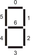
The diagram below gives the mapping of bits to the corresponding segment of the display. Note bit 0 is the LSB, bit 6 the MSB.
When you have this working, instantiate the module a second time so that pressing KEY[3] increments it, and pressing
KEY[2] decrements it, with the counter value being displayed on HEX3 and HEX2. The counters (with slight
modifications) will eventually be used to control the positions of the bats on the screen.
|