Robot Assembly
Difficulty: introduction
This tutorial shows you how to put together the robot chassis from a kit. Only basic tools are required. For more information on where to get a kit, see here.
REQUIREMENTS:
-
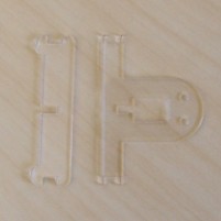
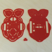 Top and bottom plates
 -
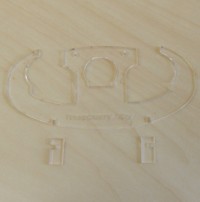 Bumper
 -
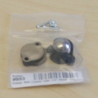
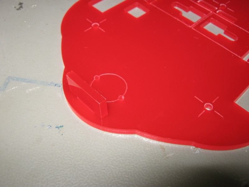
 Coil holder
 -
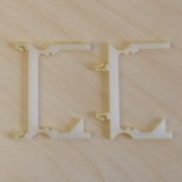 Board clips
 -
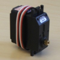 Servo x 2
 -
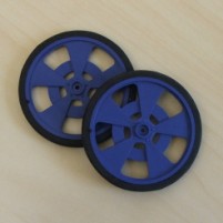 Wheel x 2
 -
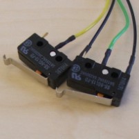 Microswitch x 2
 -
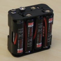 Battery pack
 -
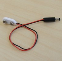 PP3 battery snap
 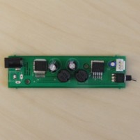 Regulator board
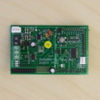 Custom Pi shield
-
 0.5” ball caster x 2
 -
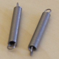 Spring x 2
 -
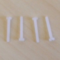
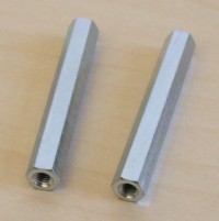 40mm M3 spacer x 5
 -
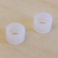 3mm M3 spacer x 2
 -
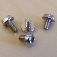 6mm M3 screw x 10
 -
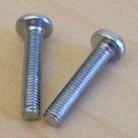 20mm M3 screw x 6
 -
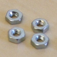
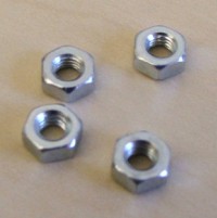 M3 nut x 6
 -
 M3 washer x 4
 -
 16mm M2 screw x 8
 -
 M2 nut x 8
 -
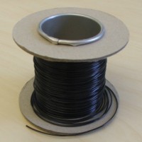 Insulated wire
 -
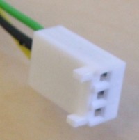 0.1” crimp housing (3 pin)
 -
 Phillips head screwdriver
INSTRUCTIONS:
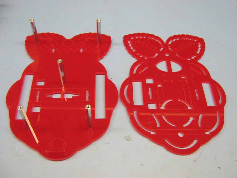
Clip the battery pack retainer into the top side of the bottom plate. The bottom plate is the one with larger slots for the wheels. The top side is the one with lines and shapes etched into it.
At each of the points marked with a cross, screw a 40mm spacer to the top side of the bottom plate using a 6mm M3 screw.
Attach casters to the underside of the bottom plate at the positions marked with circles using M2 screws and nuts.
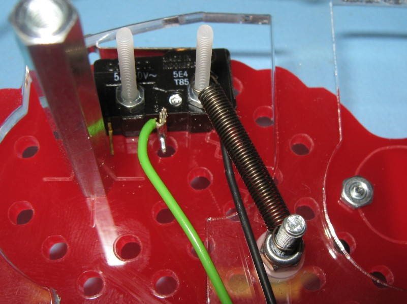
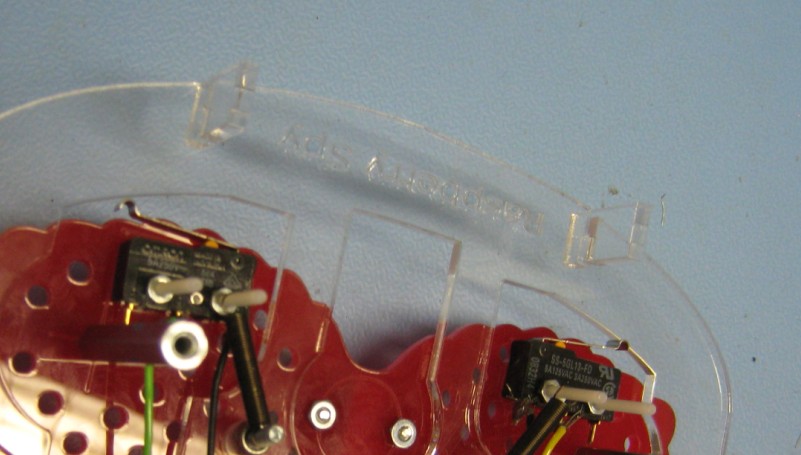
Attach wires to the “common” (COM) terminal and the “normally open” (NO) terminal of each switch. The “normally closed” (NC) terminal is not required. Here, black wires have been used for the common terminals, as they will share a single connection to the Raspberry Pi.
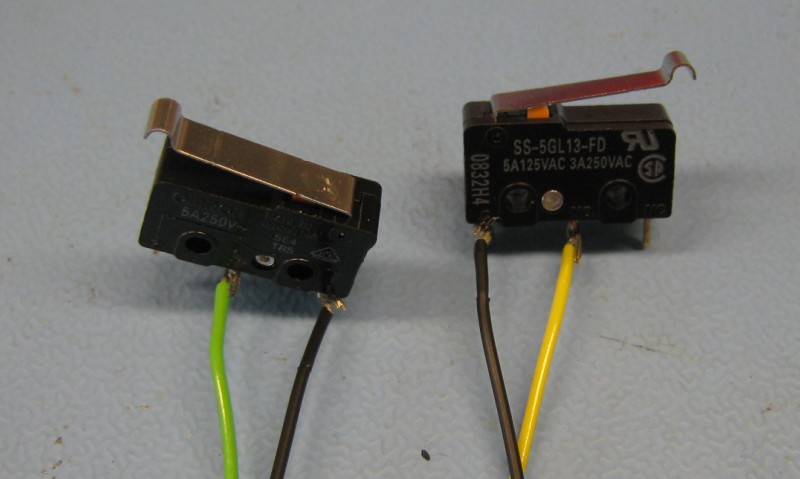
Crimp the other ends of the wires (and connect the two common lines together).
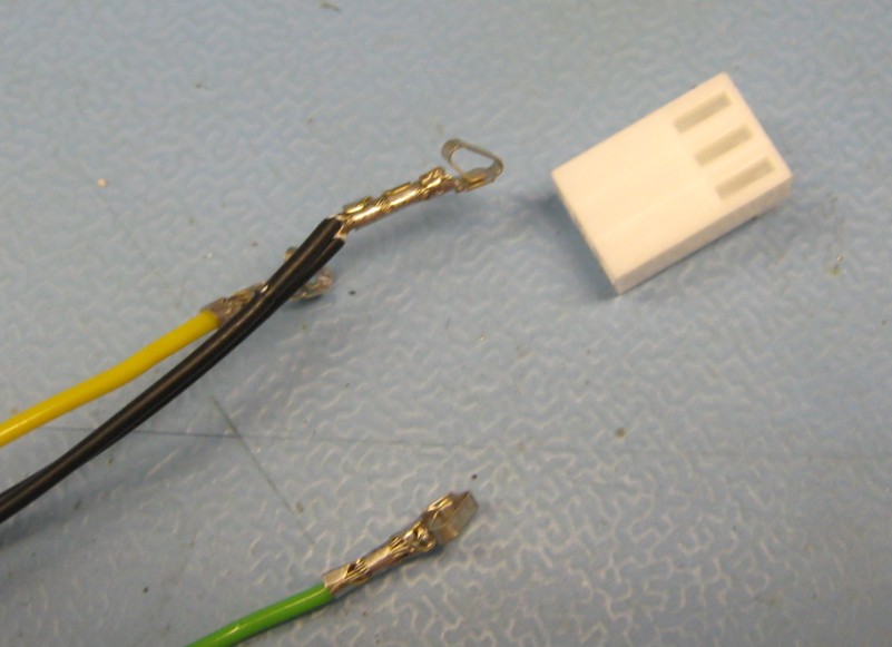
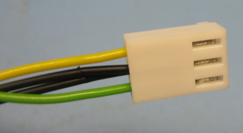
Plug the wires into the crimp housing.
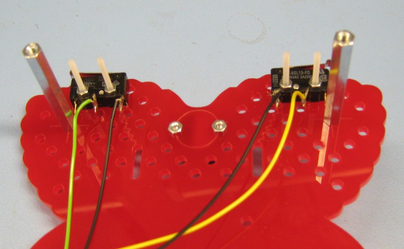
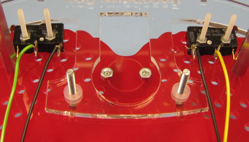
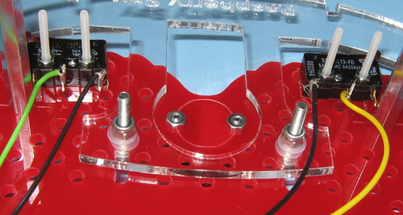
Using M2 screws and nuts, attach the switches to the top side of the bottom plate. Rectangles etched into the plate show the correct positions.
Push two 20mm M3 screws up through the slots in the bottom plate, then put on a washer, the bumper, and a second washer.
Secure the bumper with M3 nuts. Do not over-tighten: the bumper should still move backwards and forwards quite freely.
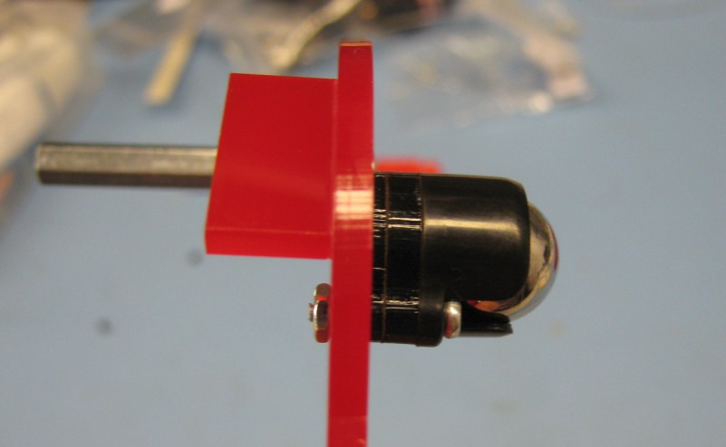
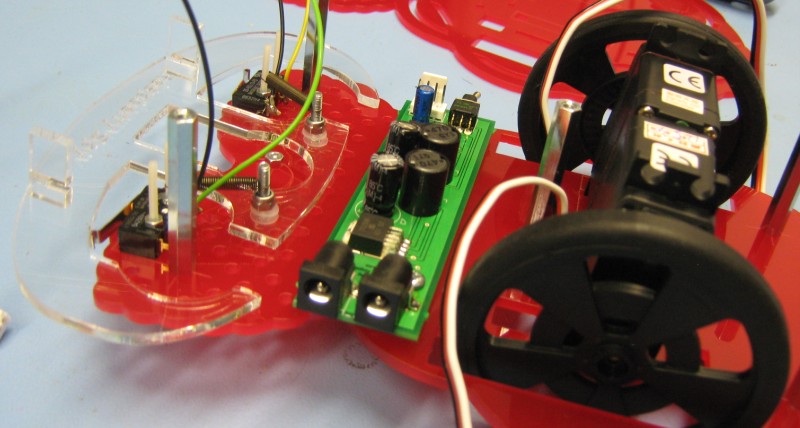
Attach a wheel to each servo, and place them in position on the top side of the bottom plate. The wires should go through the holes so that they are not in the way.
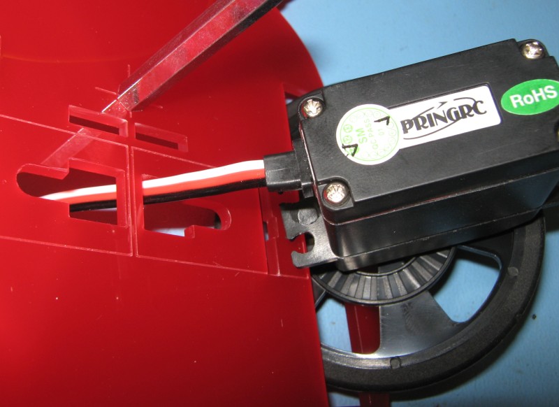
Push the servo leads back up through the nearby slots so they do not drag along the floor.
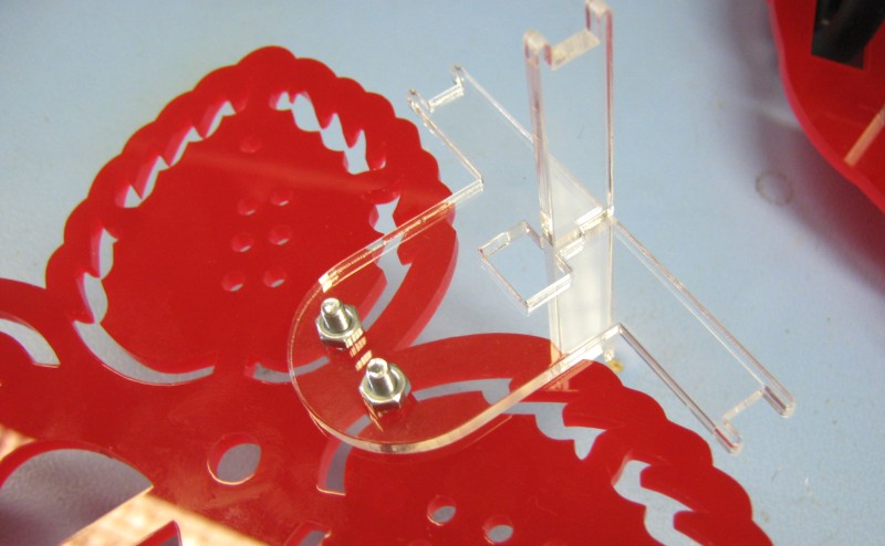
Attach springs to each side of the bumper. Zigzag lines on the bottom plate show the position. The bumper should be easy to depress on the left side, right side, and both sides at once. It should return to a non-depressed state when it is not being pressed.
Attach the bumper uprights to the bumper. These stop one bumper getting stuck on top of another in the event of two robots colliding.
Attach the regulator board as shown using 20mm M3 screws and 3mm M3 spacers between the bottom plate and the board.
Weave the battery snap lead through the two square holes either side of the servos, and plug it into either power jack on the regulator board.
Slot the battery pack into the space behind the servos and connect the battery snap.
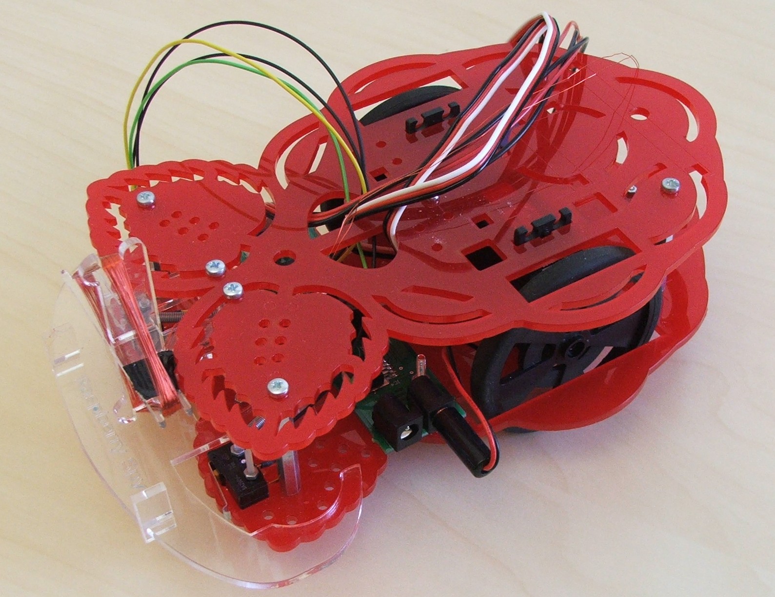
Clip the two parts of the coil holder together, and attach to the underside of the top plate using 20mm M3 screws and nuts.
Attach the top plate to the bottom plate by screwing it in to the spacers with 6mm M3 screws. Pull all of the leads up through the holes shown to make them more accessible.
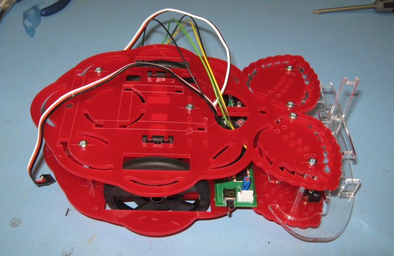
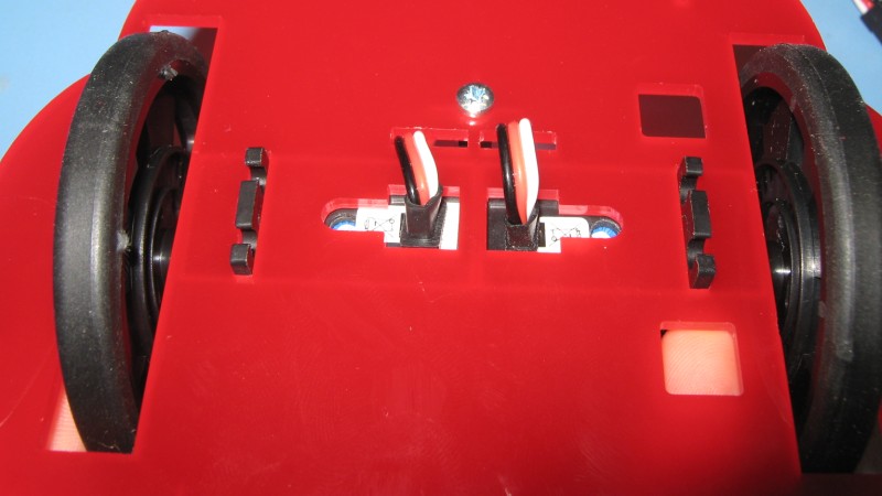
Attach the board clips to the top of the robot.
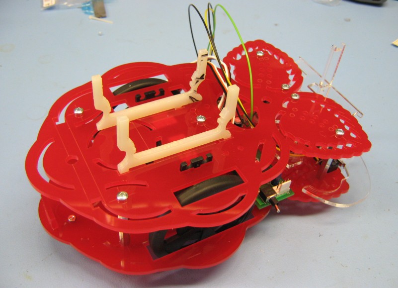
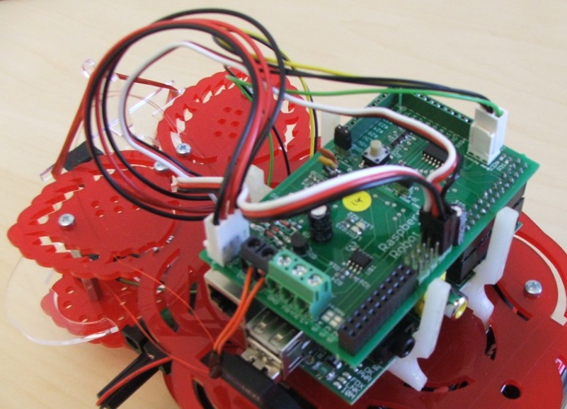
Clip a shield into place (possibly with a Raspberry Pi) and connect all of the loose wires. From left-to-right these connections are:
- 4 pin power connection to regulator board
- 2 NFC coil connections (optional)
- Right motor
- Left motor
- 3 pin connection to microswitches