
Raspberry Pi
Lesson 3 OK03
The OK03 lesson builds on OK02 by teaching how to use functions in assembly to make more reusable and rereadable code. It is assumed you have the code for the Lesson 2: OK02 operating system as a basis.
Contents |
1 Reusable Code
So far we've made code for our operating system by typing the things we want to happen in order. This is fine for such tiny programs, but if we wrote the whole system like this, the code would be completely unreadable. Instead we use functions.

Functions are said to be 'black boxes'. We put inputs in, and outputs come out, but we don't need to know how they work.
In higher level code such as C or C++, functions are part of the language itself. In assembly code, functions are just ideas we have.
Ideally we want to be able to set our registers to some input values, branch to an address, and expect that at some point the code will branch back to our code having set the registers to output values. This is what a function is in assembly code. The difficulty comes in what system we use for setting the registers. If we just used any system we felt like, each programmer may use a different system, and would find other programmers' work hard to understand. Further, compilers would not be able to work with assembly code as easily, as they would not know how to use the functions. To prevent confusion, a standard called the Application Binary Interface (ABI) was devised for each assembly language which is an agreement on how functions should be run. If everyone makes functions in the same way, then everyone will be able to use each others' functions. I will teach that standard here, and from now on I will code all of my functions to meet the standard.
The standard says that r0,r1,r2 and r3 will be used as inputs to a function in order. If a function needs no inputs, then it doesn't matter what value it takes. If it needs only one it always goes in r0, if it needs two, the first goes in r0, and the second goes on r1, and so on. The output will always be in r0. If a function has no output, it doesn't matter what value r0 takes.
Further, it also requires that after a function is run, r4 to r12 must have the same values as they had when the function started. This means that when you call a function, you can be sure the r4 to r12 will not change value, but you cannot be so sure about r0 to r3.
When a function completes it has to branch back to the code that started it. This means it must know the address of the code that started it. To facilitate this, there is a special register called lr (link register) which always holds the address of the instruction after the one that called this function.
| Register | Brief | Preserved | Rules |
|---|---|---|---|
| r0 | Argument and result | No | r0 and r1 are used for passing the first two arguments to functions, and returning the results of functions. If a function does not use them for a return value, they can take any value after a function. |
| r1 | Argument and result | No | |
| r2 | Argument | No | r2 and r3 are used for passing the second two arguments to functions. There values after a function is called can be anything. |
| r3 | Argument | No | |
| r4 | General purpose | Yes | r4 to r12 are used for working values, and their value after a function is called must be the same as before. |
| r5 | General purpose | Yes | |
| r6 | General purpose | Yes | |
| r7 | General purpose | Yes | |
| r8 | General purpose | Yes | |
| r9 | General purpose | Yes | |
| r10 | General purpose | Yes | |
| r11 | General purpose | Yes | |
| r12 | General purpose | Yes | |
| lr | Return address | No | lr is the address to branch back to when a function is finished, but this does have to contain the same address after the function has finished. |
| sp | Stack pointer | Yes | sp is the stack pointer, described below. Its value must be the same after the function has finished. |
Often functions need to use more registers than just r0 to r3. But, since r4 to r12 must stay the same after the method has run, they must be saved somewhere. We save them on something called the stack.
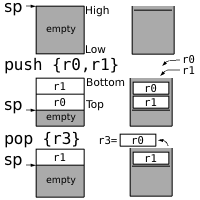
A stack is a metaphor we use in computing for a method of storing values. Just like in a stack of plates, you can only remove items from the top of a stack, and only add items to the top of the stack.
The stack is a brilliant idea for storing registers on when functions are running. For example if I have a function which needs to use registers r4 and r5, it could place the current values of those registers on a stack. At the end of the method it could take them back off again. What is most clever is that if my function had to run another function in order to complete and that function needed to save some registers, it could put those on the top of the stack while it ran, and then take them off again at the end. That wouldn't affect the values of r4 and r5 that my method had to save, as they would be added to the top of the stack, and then taken off again.
The terminology we used to refer to the values put on the stack by a particular method is that methods 'stack frame'. Not every method needs a stack frame, some don't need to store values.
Because the stack is so useful, it has been implemented in the ARMv6 instruction set directly. A special register called sp (stack pointer) holds the address of the stack. When items are added to the stack, the sp register updates so that it always holds the address of the first item on the stack. push {r4,r5} would put the values in r4 and r5 onto the top of the stack and pop {r4,r5} would take them back off again (in the correct order).
2 Our First Function
Now that we have some idea about how functions work, let's try to make one. For a basic first example, we are going to make a function that takes no input, and gives an output of the GPIO address. In the last lesson, we just wrote in this value, but it would be better as a function, since it is something we might need to do often in a real operating system, and we might not always remember the address.
Copy the following code into a new file called 'gpio.s'. Just make the new file in the 'source' directory with 'main.s'. We're going to put all functions related to the GPIO controller in one file to make them easier to find.
.globl GetGpioAddress
GetGpioAddress:
ldr r0,=0x20200000
mov pc,lr
.globl lbl makes the label lbl accessible from other files.
mov reg1,reg2 copies the value in reg2 into reg1.
This is a very simple complete function. The .globl GetGpioAddress command is a message to the assembler to make the label GetGpioAddress accessible to all files. This means that in our main.s file we can branch to the label GetGpioAddress even though it is not defined in that file.
You should recognise the ldr r0,=0x20200000 command, which stores the GPIO controller address in r0. Since this is a function, we have to give the output in r0, so we are not as free to use any register as we once were.
mov pc,lr copies the value in lr to pc. As mentioned earlier lr always contains the address of the code that we have to go back to when a method finishes. pc is a special register which always contains the address of the next instruction to be run. A normal branch command just changes the value of this register. By copying the value in lr to pc we just change the next line to be run to be the one we were told to go back to.
A reasonable question would now be, how would we actually run this code? A special type of branch bl does what we need. It branches to a label like a normal branch, but before it does it updates lr to contain the address of the line after the branch. That means that when the function finishes, the line it will go back to will be the one after the bl command. This makes a function running just look like any other command, it simply runs, does whatever it needs to do, and then carries on to the next line. This is a really useful way of thinking about functions. We treat them as 'black boxes' in that when we use them, we don't need to think about how they work, we just need to know what inputs they need, and what outputs they give.
For now, don't worry about using the function, we will use it in the next section.
3 A Big Function
Now we're going to implement a bigger function. Our first job was to enable output on GPIO pin 16. It would be nice if this was a function. We could simply specify a pin and a function as the input, and the function would set the function of that pin to that value. That way, we could use the code to control any GPIO pin, not just the LED.
Copy the following commands below the GetGpioAddress function in gpio.s.
.globl SetGpioFunction
SetGpioFunction:
cmp r0,#53
cmpls r1,#7
movhi pc,lr
Suffix ls causes the command to be executed only if the last comparison determined that the first number was less than or the same as the second. Unsigned.
Suffix hi causes the command to be executed only if the last comparison determined that the first number was higher than the second. Unsigned.
One of the first things we should always think about when writing functions is our inputs. What do we do if they are wrong? In this function, we have one input which is a GPIO pin number, and so must be a number between 0 and 53, since there are 54 pins. Each pin has 8 functions, numbered 0 to 7 and so the function code must be too. We could just assume that the inputs will be correct, but this is very dangerous when working with hardware, as incorrect values could cause very bad side effects. Therefore, in this case, we wish to make sure the inputs are in the right ranges.
To do this we need to check that r0 <= 53 and r1 <= 7. First of all, we can use the comparison we've seen before to compare the value of r0 with 53. The next instruction, cmpls is a normal comparison instruction that will only be run if r0 was lower than or the same as 53. If that was the case, it compares r1 with 7, otherwise the result of the comparison is the same as before. Finally we go back to the code that ran the function if the result of the last comparison was that the register was higher than the number.
The effect of this is exactly what we want. If r0 was bigger than 53, then the cmpls command doesn't run, but the movhi does. If r0 is <= 53, then the cmpls command does run, and so r1 is compared with 7, and then if it is higher than 7, movhi is run, and the function ends, otherwise movhi does not run, and we know for sure that r0 <= 53 and r1 <= 7.
There is a subtle difference between the ls (lower or same) and le (less or equal) as well as between hi (higher) and gt (greater) suffixes, but I will cover this later.
Copy these commands below the above.
push {lr}
mov r2,r0
bl GetGpioAddress
push {reg1,reg2,...} copies the registers in the list reg1,reg2,... onto the top of the stack. Only general purpose registers and lr can be pushed.
bl lbl sets lr to the address of the next instruction and then branches to the label lbl.
These next three commands are focused on calling our first method. The push {lr} command copies the value in lr onto the top of the stack, so that we can retrieve it later. We must do this because when we call GetGpioAddress, we will need to use lr to store the address to come back to in our function.
If we did not know anything about the GetGpioAddress function, we would have to assume it changes r0,r1,r2 and r3, and would have to move our values to r4 and r5 to keep them the same after it finishes. Fortunately, we do know about GetGpioAddress, and we know it only changes r0 to the address, it doesn't affect r1,r2 or r3. Thus, we only have to move the GPIO pin number out of r0 so it doesn't get overwritten, but we know we can safely move it to r2, as GetGpioAddress doesn't change r2.
Finally we use the bl instruction to run GetGpioAddress. Normally we use the term 'call' for running a function, and I will from now. As discussed earlier bl calls a function by updating the lr to the next instruction's address, and then branching to the function.
When a function ends we say it has 'returned'. When the call to GetGpioAddress returns, we now know that r0 contains the GPIO address, r1 contains the function code and r2 contains the GPIO pin number. I mentioned earlier that the GPIO functions are stored in blocks of 10, so first we need to determine which block of ten our pin number is in. This sounds like a job we would use a division for, but divisions are very slow indeed, so it is better for such small numbers to do repeated subtraction.
Copy the following code below the above.
functionLoop$:
cmp r2,#9
subhi r2,#10
addhi r0,#4
bhi functionLoop$
add reg,#val adds the number val to the contents of the register reg.
This simple loop code compares the pin number to 9. If it is higher than 9, it subtracts 10 from the pin number, and adds 4 to the GPIO Controller address then runs the check again.
The effect of this is that r2 will now contain a number from 0 to 9 which represents the remainder of dividing the pin number by 10. r0 will now contain the address in the GPIO controller of this pin's function settings. This would be the same as GPIO Controller Address + 4 × (GPIO Pin Number ÷ 10).
Finally, copy the following code below the above.
add r2, r2,lsl #1
lsl r1,r2
str r1,[r0]
pop {pc}
Argument shift reg,lsl #val shifts the binary representation of the number in reg left by val before using it in the operation before.
lsl reg,amt shifts the binary representation of the number in reg left by the number in amt.
str reg,[dst] is the same as str reg,[dst,#0].
pop {reg1,reg2,...} copies the values from the top of the stack into the register list reg1,reg2,.... Only general purpose registers and pc can be popped.
This code finishes off the method. The first line is actually a multiplication by 3 in disguise. Multiplication is a big and slow instruction in assembly code, as the circuit can take a long time to come up with the answer. It is much faster sometimes to use some instructions which can get the answer quicker. In this case, I know that r2 × 3 is the same as r2 × 2 + r2. It is very easy to multiply a register by 2 as this is conveniently the same as shifting the binary representation of the number left by one place.
One of the very useful features of the ARMv6 assembly code language is the ability to shift an argument before using it. In this case, I add r2 to the result of shifting the binary representation of r2 to the left by one place. In assembly code, you often use tricks such as this to compute answers more easily, but if you're uncomfortable with this, you could also write something like mov r3,r2; add r2,r3; add r2,r3.
Now we shift the function value left by a number of places equal to r2. Most instructions such as add and sub have a variant which uses a register rather than a number for the amount. We perform this shift because we want to set the bits that correspond to our pin number, and there are three bits per pin.
We then store the the computed function value at the address in the GPIO controller. We already worked out the address in the loop, so we don't need to store it at an offset like we did in OK01 and OK02.
Finally, we can return from this method call. Since we pushed lr onto the stack, if we pop pc, it will copy the value that was in lr at the time we pushed it into pc. This would be the same as having used mov pc,lr and so the function call will return when this line is run.
The very keen may notice that this function doesn't actually work correctly. Although it sets the function of the GPIO pin to the requested value, it causes all the pins in the same block of 10's functions to go back to 0! This would likely be quite annoying in a system which made heavy use of the GPIO pins. I leave it as a challenge to the interested to fix this function so that it does not overwrite other pins values by ensuring that all bits other than the 3 that must be set remain the same. A solution to this can be found on the downloads page for this lesson. Functions that you may find useful are and which computes the Boolean and function of two registers, mvns which computes the Boolean not and orr which computes the Boolean or.
4 Another Function
So, we now have a function which takes care of the GPIO pin function setting. We now need to make a function to turn a GPIO pin on or off. Rather than having one function for off and one function for on, it would be handy to have a single function which does either.
We will make a function called SetGpio which takes a GPIO pin number as its first input in r0, and a value as its second in r1. If the value is 0 we will turn the pin off, and if it is not zero we will turn it on.
Copy and paste the following code at the end of 'gpio.s'.
.globl SetGpio
SetGpio:
pinNum .req r0
pinVal .req r1
alias .req reg sets alias to mean the register reg.
Once again we need the .globl command and the label to make the function accessible from other files. This time we're going to use register aliases. Register aliases allow us to use a name other than just r0 or r1 for registers. This may not be so important now, but it will prove invaluable when writing big methods later, and you should try to use aliases from now on. pinNum .req r0 means that pinNum now means r0 when used in instructions.
Copy and paste the following code after the above.
cmp pinNum,#53
movhi pc,lr
push {lr}
mov r2,pinNum
.unreq pinNum
pinNum .req r2
bl GetGpioAddress
gpioAddr .req r0
.unreq alias removes the alias alias.
Like in SetGpioFunction the first thing we must do is check that we were actually given a valid pin number. We do this in exactly the same way by comparing pinNum (r0) with 53, and returning immediately if it is higher. Once again we wish to call GetGpioAddress, so we have to preserve lr by pushing it onto the stack, and to move pinNum to r2. We then use the .unreq statement to remove our alias from r0. Since the pin number is now stored in r2 we want our alias to reflect this, so we remove the alias from r0 and remake it on r2. You should always .unreq every alias as soon as it is done with, so that you cannot make the mistake of using it further down the code when it no longer exists.
We then call GetGpioAddress, and we create an alias for r0 to reflect this.
Copy and paste the following code after the above.
pinBank .req r3
lsr pinBank,pinNum,#5
lsl pinBank,#2
add gpioAddr,pinBank
.unreq pinBank
lsr dst,src,#val shifts the binary representation of the number in src right by val, but stores the result in dst.
The GPIO controller has two sets of 4 bytes each for turning pins on and off. The first set in each case controls the first 32 pins, and the second set controls the remaining 22. In order to determine which set it is in, we need to divide the pin number by 32. Fortunately this is very easy, at is the same as shifting the binary representation of the pin number right by 5 places. Hence, in this case I've named r3 as pinBank and then computed pinNum ÷ 32. Since it is a set of 4 bytes, we then need to multiply the result of this by 4. This is the same as shifting the binary representation left by 2 places, which is the command that follows. You may wonder if we could just shift it right by 3 places, as we went right then left. This won't work however, as some of the answer may have been rounded away when we did ÷ 32 which may not be if we just ÷ 8.
The result of this is that gpioAddr now contains either 2020000016 if the pin number is 0-31, and 2020000416 if the pin number is 32-53. This means if we add 2810 we get the address for turning the pin on, and if we add 4010 we get the address for turning the pin off. Since we are done with pinBank, I use .unreq immediately afterwards.
Copy and paste the following code after the above.
and pinNum,#31
setBit .req r3
mov setBit,#1
lsl setBit,pinNum
.unreq pinNum
and reg,#val computes the Boolean and function of the number in reg with val.
This next part of the function is for generating a number with the correct bit set. For the GPIO controller to turn a pin on or off, we give it a number with a bit set in the place of the remainder of that pin's number divided by 32. For example, to set pin 16, we need a number with the 16th bit a 1. To set pin 45 we would need a number with the 13th bit 1 as 45 ÷ 32 = 1 remainder 13.
The and command computes the remainder we need. How it does this is that the result of an and operation is a number with 1s in all binary digits which had 1s in both of the inputs, and 0s elsewhere. This is a fundamental binary operation, and is very quick. We have given it inputs of pinNum and 3110 = 111112. This means that the answer can only have 1 bits in the last 5 places, and so is definitely between 0 and 31. Specifically it only has 1s where there were 1s in pinNum's last 5 places. This is the same as the remainder of a division by 32. It is no coincidence that 31 = 32 - 1.
The rest of this code simply uses this value to shift the number 1 left. This has the effect of creating the binary number we need.
Copy and paste the following code after the above.
teq pinVal,#0
.unreq pinVal
streq setBit,[gpioAddr,#40]
strne setBit,[gpioAddr,#28]
.unreq setBit
.unreq gpioAddr
pop {pc}
teq reg,#val checks if the number in reg is equal to val.
This code ends the method. As stated before, we turn the pin off if pinVal is zero, and on otherwise. teq (test equal) is another comparison operation that can only be used to test for equality. It is similar to cmp but it does not work out which number is bigger. If all you wish to do is test if to numbers are the same, you can use teq.
If pinVal is zero, we store the setBit at 40 away from the GPIO address, which we already know turns the pin off. Otherwise we store it at 28, which turns the pin on. Finally, we return by popping the pc, which sets it to the value that we stored when we pushed the link register.
5 A New Beginning
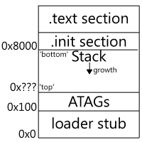
Finally, after all that work we have our GPIO functions. We now need to alter 'main.s' to use them. Since 'main.s' is now getting a lot bigger and more complicated, it is better design to split it into two sections. The '.init' we've been using so far is best kept as small as possible. We can change the code to reflect this easily.
Insert the following just after _start: in main.s:
b main
.section .text
main:
mov sp,#0x8000
The key change we have made here is to introduce the .text section. I have designed the makefile and linker scripts such that code in the .text section (which is the default section) is placed after the .init section which is placed at address 800016. This is the default load address and gives us some space to store the stack. As the stack exists in memory, it has to have an address. The stack grows down memory, so that each new value is at a lower address, thus making the 'top' of the stack, the lowest address.
The 'ATAGs' section in the diagram is a place where information about the Raspberry Pi is stored such as how much memory it has, and what its default screen resolution is.
Replace all the code that set the function of the GPIO pin with the following:
pinNum .req r0
pinFunc .req r1
mov pinNum,#16
mov pinFunc,#1
bl SetGpioFunction
.unreq pinNum
.unreq pinFunc
This code calls SetGpioFunction with the pin number 16 and the pin function code 1. This has the effect of enabling output to the OK LED.
Replace any code which turns the OK LED on with the following:
pinNum .req r0
pinVal .req r1
mov pinNum,#16
mov pinVal,#0
bl SetGpio
.unreq pinNum
.unreq pinVal
This code uses SetGpio to turn off GPIO pin 16, thus turning on the OK LED. If we instead used mov pinVal,#1, it would turn the LED off. Replace your old code to turn the LED off with that.
6 Onwards
Hopefully now, you should be able to test what you have made on the Raspberry Pi. We've done a large amount of code this time, so there is a lot that can go wrong. If it does, head to the troubleshooting page.
When you get it working, congratulations. Although our operating system does nothing more than it did in Lesson 2: OK02, we've learned a lot about functions and formatting, and we can now code new features much more quickly. It would be very simple now to make an Operating System that alters any GPIO register, which could be used to control hardware!
In Lesson 4: OK04, we will address our wait function, which is currently imprecise, so that we can gain better control over our LED, and ultimately over all of the GPIO pins.
Spot a mistake? You can help improve this tutorial on GitHub.

Baking Pi: Operating Systems Development by Alex Chadwick is licensed under a Creative Commons Attribution-ShareAlike 3.0 Unported License.
Based on contributions at https://github.com/chadderz121/bakingpi-www.