Using a Breadboard
Difficulty: introduction
A breadboard is a very useful device for prototyping circuits. It allows you to easily plug in and remove components and so if there are going to be many changes or if you just want to make a circuit quickly, it will be much quicker than soldering up your circuit.
This tutorial will only be necessary for those who have never used a breadboard before or are not confident using one. It will guide you through how a breadboard works and how to make a very simple circuit.
REQUIREMENTS:
BACKGROUND:
See the breadboard page for information on the internals of a breadboard.
INSTRUCTIONS:
First we’ll plug in the breakout board. The important thing here is to make sure that the two rows of pins end up on different sides of the bridge in the middle, otherwise you could damage your Pi when you connect it. Make sure that the pins are aligned with the holes and push down firmly. It should clip into place and the pins should now be below the plastic.
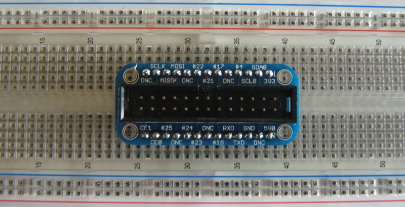 Breakout board clipped in place.
Next we’ll connect the 3.3V (3V3 pin) to the power rail and ground (GND pin) to the ground rail. This isn’t completely necessary and we won’t make use of it for our circuit but it is good practice and will normally make a breadboard easier to use and help to identify problems. In the picture, the power rails on each side of the board are also connected.
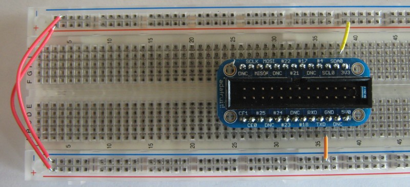 Power rails connected.
Now let’s wire up an LED to one of the GPIO pins. Once this is done you’ll have the circuit for the morse code tutorial so we suggest you have a go at that when done. Connecting up an LED requires making sure the LED is the right way round (the flat side with the short lead goes to ground) and that it doesn’t draw so much current that it burns itself out so we put a current-limting resistor in place.
The columns are connected together so we cannot just put everything in one column. This would mean there is no voltage across the LED so it won’t light up, instead there is only a path from the GPIO pin to ground through the resistor: not what we want.
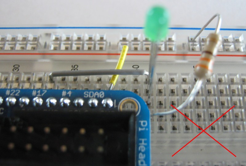 The LED’s two leads are connected to the same column so it will not light up.
The correct way to wire things up is to have a jumper from one of the GPIO pins to a free column, then the positive side of the LED in that same column and the ground in the adjacent one. Then use the resistor to connect the ground of the LED to the ground of the Pi by placing one end in the same column as the LED ground and the other in the ground rail.
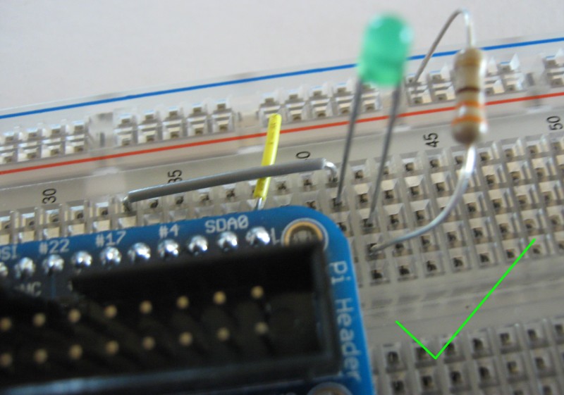 If your circuit looks like this, everything should work.
Now you can plug in your Pi using the ribbon cable. Make sure the red stripe goes to the outside edge of the board. Try out the morse code example on the Pi or follow the tutorial to test it out.
