
ECAD and Architecture Practical Classes
Thacker's Tiny Computer 3
Turing award winner Charles (Chuck) Thacker has many decades of experience designing computer systems. He designed the Tiny Computer 3 in 2007 as a teaching aid - see the PDF paper. This paper presents the design design in a schematic form which is then implemented using primarily structural Verilog with Xilinx specific buffers and RAM blocks.
For these Labs we'll be using a SystemVerilog variant we've designed in-house - see ttc.sv. A more behavioural style is used which is more amenable to modification (e.g. adding a multiplier) and is more portable without sacrificing area. Rather than use a two phase clocking scheme we've stuck with a single phase clock using only the positive edge. This incurs a small performance penalty. We only needed a ROM for instruction memory so store-to-instruction-memory has been removed. Data memory (unused in these Labs) is provided via an Altera Avalon memory-mapped master interface. In and Out channels have been turned into Avalon Streaming interfaces so that the design can be dropped into Altera's Qsys system builder tool - see Lab 2 for details, including an assembler and simulation environment.
TTC Assembler Guide
We've written a very simple TTC assembler in Java - ttcasm.jar. See the Lab. 1 instructions if you need help downloading and using this Java code.
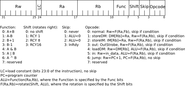
The Computer Design course discusses the architecture of the processor and presents the following illustration of the instruction format.
Spacing
Any text at the start of a line is assumed to be a label. Instructions should be prefixed by some white space, e.g. a tab.
Registers
There are 128 registers named r0 through r127. The registers are all general purpose. Registers are specified in the sequence: rw ra rb where rw is the destination register (the one written to), ra is operand A and rb is operand B.
Loading Constants
The lc instruction loads constants, e.g. r4=345 would be written as:
lc r4 345
Note that numbers out of range are currently truncated without giving a warning. Constants are unsigned and are at most 24-bit long
Function
The Function field specifies what arithmetic or logical operation is to be performed. Here are the assembler mnemonics:
- add
- sub
- inc
- dec
- and
- or
- xor
Examples:
- Add register r1 and r2 and put the result in r3,
i.e. r3=r1+r2:
add r3 r1 r2 - The function can also be placed at the end, e.g. the following are
identical
add r3 r1 r2
r3 r1 r2 add - Increment r5:
inc r5 - Move register r3 into r1, i.e. r3=r1 which can be coded as r3=r1 & r1:
and r3 r1 r1
Shifts (rotates)
The result of the Function (as specified above) is then fed to a shifter. Actually this is a barrel rotator which can perform the following rotations:
- no shift - just leave blank for no shift
- >>1 - rotate right by 1 bit
- >>8 - rotate right by 8 bits
- >>16 - rotate right by 16 bits
Example: load a 32-bit constant from two 16-bit
constants: r2=(r2<<16) | r1 but using rotate right 16 rather than
shift left by 16:
lc r1 1024
lc r2 256
and r2 r2 r2 >>16
or r2 r2 r1
This would give the result (256<<16) | 1024 = (0x100<<16) | 0x400 = 0x01000400
Opcodes
The opcode specifies the family of instruction used using a token (a character sequence with no spaces inside the token):
- normal: arithmetic/logical instructions are classed as "normal" which is the default for the instruction if no opcode is specified.
- storeDM: store to data memory is specified using the ->dm token. Note that for Lab 2 there is no data memory since all of the operations can be performed in registers so the data memory was removed to save space.
- storeIM: store to instruction memory is specified using the ->im token. Note that this is not supported on the current ttc.sv design since code is provided in a ROM and the instruction has been removed to save area.
- out sends the ALU result to the output communication channel and is specified using the ->out token. In Lab 2 the data is sent over a ring network to a Nios host processor.
- loadDM loads data from memory using the address in rb and is specified using the <-dm token.
- in reads the input channel (Avalon input stream) and places the result in rw and is specified using the <-in token.
- jump writes to the program counter (PC) to change the flow of control. The PC is assigned the output of the arithmetic operation. rw is assigned the PC value after the jump to facilitate subroutine calls. Jump is specified by the jmp token.
Examples
- Store r1 to the data memory at the address in r2 (r0 is trashed):
(NOT SUPPORTED in ttc.sv)
and r0 r1 r2 ->dm - Store r1 to the instruction memory at the address in r2 (r0 is
trashed): (NOT SUPPORTED in ttc.sv)
and r0 r1 r2 ->im - Send r1 to the output channel (r0 is scratch):
r0 r1 ->out - r1=r2+r3 and send r1 to the output channel:
add r1 r2 r3 ->out - Load from data memory at address r1 and put the result in r2
ignoring r0: (NOT SUPPORTED on ttc.sv)
r2 r0 r1 <-dm - In from the input channel:
r1 <-in - Jump to r1 and put the return address in r2:
and r2 r1 r1 jmp
or:
jmp r2 r1
Skip
The next instruction can be conditionally skipped, where the skip is specified as follows:
- never/no skip - leave blank
- ALU<0 - result less than zero - ?<0
- ALU==0 - result is zero - ?==0
- InRdy - input is ready - ?in
Example: loop 10 times:
# my register usage:
# r0 = scratch register
# r1 = jump target
# r2 = loop counter
        lc r1 loop   # r1 = address of "loop" label
        lc r2 10
loop:   dec r2 ?==0
	jmp r0 r1
Example: r1=(r1>r2) ? r1 : r2 (and r0 is scratch):
        sub r0 r2 r1 ?<0
        and r1 r2 r2
Example: if top bit of r1 is set, r2=r2+r3:
        and r1 r1 r1 ?<0
        sub r2 r2 r3
        add r2 r2 r3
Labels
Like most assemblers, labels are provided to mark point in the code as jump targets. See the Skip example above for an example.
Comments
Comments start with a # and continue until the end of the line.