Orangepath/HPR Logic Synthesis Project: Hardware and Embedded Software Synthesis
from Executable Specifications.
Compilation from .net CIL Bytecode (second example)
Kiwi: Synthesis from .net CIL Bytecode (offchip example)
High-level Synthesis of Sieve of Eratosthenes
In this example, the following C# program was compiled to .net CIL bytecode.
The program counts the number of primes below a limit of 10000.
It was compiled in two ways: with an on-chip and with an off-chip array/memory.
Arrays allocated by the C# code are converted into an appropriate memory technology based on their size.
There are a number of (adjustable) threshold values that select what sort of RAM to target.
All but the largest are converted to Verilog array definitions that compile to on-chip RAMs using today's FPGA tools.
Very large RAMS are placed off chip by default.
The memory technologies are:
- 1. unstructured: no read or write busses are generated (sea of flip-flops)
- 2. combinational read, synchronous write register file (address
generated in same cycle as read data consumed)
- 3. latency of 1 SSRAM (address generated one clock cycle before
read data used)
- 4. external memory interface for offchip ZBT, DRAM, or cached DRAM.
The FPGA tools will generally automatically choose whether to use a
register file for a distributed RAM for forms 1 and 2. They will
infer BRAM (or Altera equivalent) for 3. Larger arrays must be placed
in off-chip SRAM or DRAM banks.
In addition to comparing sizes against compilation thresholds, the user can add an attribute to instances (OutboardArray or SynchSRAM(n)) to force a given technology choice on a per-RAM basis.
In this example, the off-chip array was synthesised not because it was large
but because the source code was marked up with a Kiwi attribute on the definition of the array.
In addition, we manually specified the base address and the port name for the external connection.
In general, arrays can be mapped to a specific bank by giving the bank name and leaving out the base address. KiwiC will then allocate the base addresses for each memory to avoid overlaps.
If no bank name is given, then a default of 'drambank0' is automatically supplied. Therefore, without using any attributes, all large arrays are mapped into consecutive locations
of a memory space called 'drambank0'. It is up to the system architect what sort of memory to attach to the resulting port: it could range from simple large SRAM bank to multiple DRAM banks with caches.
One of the log files (the h04_restructure one) contains a listing of the allocations made by KiwiC.
Offchip Memory Map
*--------------------+------+-------+--------+-----------*
| Resource           | Base | Width | Length | Portname  |
*--------------------+------+-------+--------+-----------*
| DRSX32SS_AX/CC/RP2 | 0x64 | 32    | 0x64   | drambank0 |
| DRSX32SS_AX/CC/RP1 | 0x0  | 32    | 0x64   | drambank0 |
| DRSX32SS_AX/CC/RP0 | 0xc8 | 32    | 0x64   | portx     |
| DRSX1US_AX/CC/SOL  | 0x64 | 32    | 0x64   | portx     |
*--------------------+------+-------+--------+-----------*
C# Source Code: Primes
//
// Correct output is:
//   There are 1231 primes below the natural number 10000.
class primes
{
    static int limit = 10000;

    [Kiwi.OutboardArray("portx", 32768)]
    static bool [] PA = new bool[limit];

    [Kiwi.InputWordPort(31, 0)] static int vol;
    [Kiwi.OutputWordPort(31, 0)] static int count = 0;

    public static void Main()
    {
 	Console.WriteLine("Primes Up To " + limit);
	PA[0] = vol > 0;
        // Clear array
        for (int w = 0; w < limit; w++) { Kiwi.Pause(); PA[w] = true; }

	int i, j;
	// Cross off the multiples
	for (i=2;i<limit; i++)
	{
	  Kiwi.Pause();
	  for (j=i*2; j<limit; j+=i) { Kiwi.Pause(); PA[j] = false; }
        }

	// Count how many there were.
        for (int w = 0; w < limit; w++) { Kiwi.Pause(); if (PA[w]) count += 1; }
    	Console.WriteLine("There are {0} primes below the natural number {1}.", count, limit);

	}
    }
// eof
Verilog Output
The Verilog RTL that was output is as follows:
Verilog Listing: On-chip array.
Verilog Listing: Off-chip array.
The protocol used here was a variant of OCP's BVCI protocol, but others
are also supported already.
The Verilog was placed in a simple testbench that provides clock
and reset. The simulator was then run with a suitable testwrapper.
Verilog Listing: BVCI testwrapper.
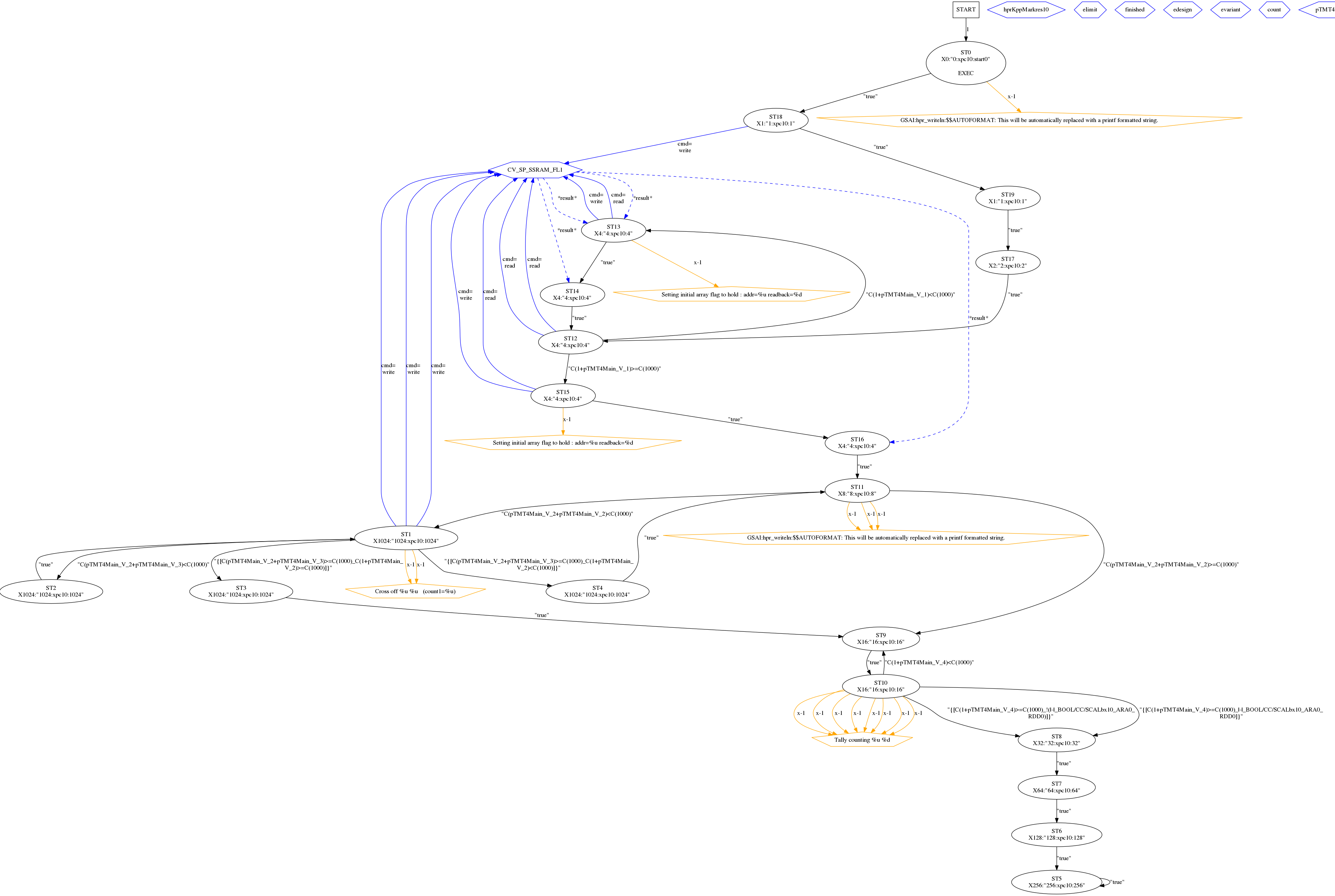
State Trajectory Plot
The Kiwi performance predictor uses a model state transition diagram and visit ratios to predict runtime.
Black arcs indicate state trajectories. Blue arcs indicate operations on structural resources such as ALUs and RAMs.
Simulation Output
The console output from the simulator was:
Monitor primes_count=1231
Finish, primes_count=1231
FPGA Schematic
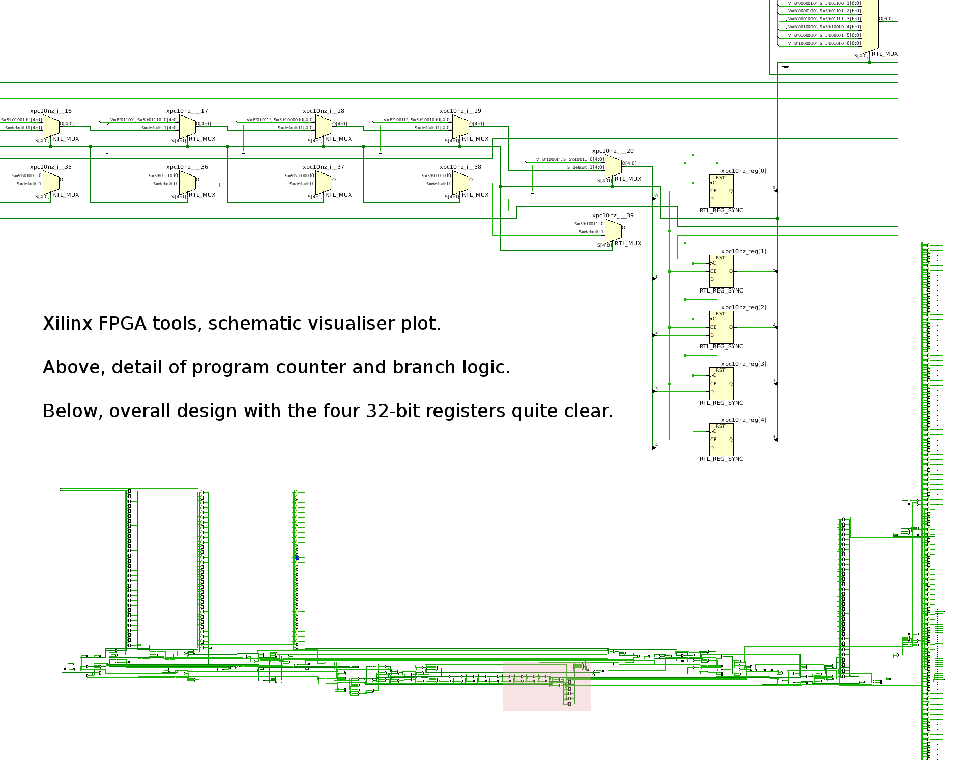
Updated May 2011.
UP.