
Raspberry Pi
Lesson 6 Screen01
Welcome to the Screen lesson series. In this series, you will learn how to control the screen using the Raspberry Pi in assembly code, starting at just displaying random data, then moving up to displaying a fixed image, displaying text and then formatting numbers into text. It is assumed that you have already completed the OK series, and so things covered in this series will not be repeated here.
This first screen lesson teaches some basic theory about graphics, and then applies it to display a gradient pattern to the screen or TV.
Contents |
1 Getting Started
It is expected that you have completed the OK series, and so functions in the 'gpio.s' file and 'systemTimer.s' file from that series will be called. If you do not have these files, or prefer to use a correct implementation, download the solution to OK05.s. The 'main.s' file from here will also be useful, up to and including mov sp,#0x8000. Please delete anything after that line.
2 Computer Graphics
There are a few systems for representing colours as numbers. Here we focus on RGB systems, but HSL is another common system used.
As you're hopefully beginning to appreciate, at a fundamental level, computers are very stupid. They have a limited number of instructions, almost exclusively to do with maths, and yet somehow they are capable of doing many things. The thing we currently wish to understand is how a computer could possibly put an image on the screen. How would we translate this problem into binary? The answer is relatively straightforward; we devise some system of numbering each colour, and then we store one number for every pixel on the screen. A pixel is a small dot on your screen. If you move very close, you will probably be able to make out individual pixels on your screen, and be able to see that everything image is just made out of these pixels in combination.
As the computer age advanced, people wanted more and more complicated graphics, and so the concept of a graphics card was invented. The graphics card is a secondary processor on your computer which only exists to draw images to the screen. It has the job of turning the pixel value information into light intensity levels to be transmitted to the screen. On modern computers, graphics cards can also do a lot more than that, such as drawing 3D graphics. In this tutorial however, we will just concentrate on the first use of graphics cards; getting pixel colours from memory out to the screen.
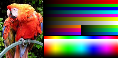
One issue that is raised immediately by all this is the system we use for numbering colours. There are several choices, each producing outputs of different quality. I will outline a few here for completeness.
Although some images here have few colours they use a technique called spatial dithering. This allows them to still show a good representation of the image, with very few colours. Many early Operating Systems used this technique.
| Name | Unique Colours | Description | Examples | |
|---|---|---|---|---|
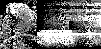
| Monochrome | 2 | Use 1 bit to store each pixel, with a 1 being white, and a 0 being black. |
|
|
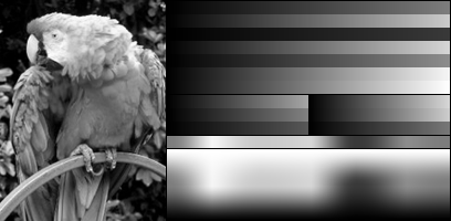
| Greyscale | 256 | Use 1 byte to store each pixel, with 255 representing white, 0 representing black, and all values in between representing a linear combination of the two. |
|
|
| 8 Colour | 8 | Use 3 bits to store each pixel, the first bit representing the presence of a red channel, the second representing a green channel and the third a blue channel. |
|
|
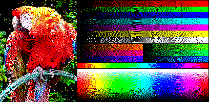
| Low Colour | 256 | Use 8 bits to store each pixel, the first 3 bit representing the intensity of the red channel, the next 3 bits representing the intensity of the green channel and the final 2 bits representing the intensity of the blue channel. |
|
|
| High Colour | 65,536 | Use 16 bits to store each pixel, the first 5 bit representing the intensity of the red channel, the next 6 bits representing the intensity of the green channel and the final 5 bits representing the intensity of the blue channel. |

|
|
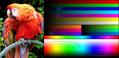
| True Colour | 16,777,216 | Use 24 bits to store each pixel, the first 8 bits representing the intensity of the red channel, the second 8 representing the green channel and the final 8 bits the blue channel. |
|
|
| RGBA32 | 16,777,216 with 256 transparency levels | Use 32 bits to store each pixel, the first 8 bits representing the intensity of the red channel, the second 8 representing the green channel, the third 8 bits the blue channel, and the final 8 bits a transparency channel. The transparency channel is only considered when drawing one image on top of another and is stored such that a value of 0 indicates the image behind's colour, a value of 255 represents this image's colour, and all values between represent a mix. | ||
In this tutorial we shall use High Colour initially. As you can see form the image, it is produces clear, good quality images, but it doesn't take up as much space as True Colour. That said, for quite a small display of 800x600 pixels, it would still take just under 1 megabyte of space. It also has the advantage that the size is a multiple of a power of 2, which greatly reduces the complexity of getting information compared with True Colour.
Storing the frame buffer places a heavy memory burden on a computer. For this reason, early computers often cheated, by, for example, storing a screens worth of text, and just drawing each letter to the screen every time it is refreshed separately.
The Raspberry Pi has a very special and rather odd relationship with it's graphics processor. On the Raspberry Pi, the graphics processor actually runs first, and is responsible for starting up the main processor. This is very unusual. Ultimately it doesn't make too much difference, but in many interactions, it often feels like the processor is secondary, and the graphics processor is the most important. The two communicate on the Raspberry Pi by what is called the 'mailbox'. Each can deposit mail for the other, which will be collected at some future point and then dealt with. We shall use the mailbox to ask the graphics processor for an address. The address will be a location to which we can write the pixel colour information for the screen, called a frame buffer, and the graphics card will regularly check this location, and update the pixels on the screen appropriately.
3 Programming the Postman
Message passing is quite a common way for components to communicate. Some Operating Systems use virtual message passing to allow programs to communicate.
The first thing we are going to need to program is a 'postman'. This is just two methods: MailboxRead, reading one message from the mailbox channel in r0. and MailboxWrite, writing the value in the top 28 bits of r0 to the mailbox channel in r1. The Raspberry Pi has 7 mailbox channels for communication with the graphics processor, only the first of which is useful to us, as it is for negotiating the frame buffer.
The following table and diagrams describe the operation of the mailbox.
| Address | Size / Bytes | Name | Description | Read / Write |
|---|---|---|---|---|
| 2000B880 | 4 | Read | Receiving mail. | R |
| 2000B890 | 4 | Poll | Receive without retrieving. | R |
| 2000B894 | 4 | Sender | Sender information. | R |
| 2000B898 | 4 | Status | Information. | R |
| 2000B89C | 4 | Configuration | Settings. | RW |
| 2000B8A0 | 4 | Write | Sending mail. | W |
In order to send a message to a particular mailbox:
- The sender waits until the Status field has a 0 in the top bit.
- The sender writes to Write such that the lowest 4 bits are the mailbox to write to, and the upper 28 bits are the message to write.
In order to read a message:
- The receiver waits until the Status field has a 0 in the 30th bit.
- The receiver reads from Read.
- The receiver confirms the message is for the correct mailbox, and tries again if not.
If you're feeling particularly confident, you now have enough information to write the two methods we need. If not, read on.
As always the first method I recommend you implement is one to get the address of the mailbox region.
.globl GetMailboxBase
GetMailboxBase:
ldr r0,=0x2000B880
mov pc,lr
The sending procedure is least complicated, so we shall implement this first. As your methods become more and more complicated, you will need to start planning them in advance. A good way to do this might be to write out a simple list of the steps that need to be done, in a fair amount of detail, like below.
- Our input will be what to write (r0), and what mailbox to write it to (r1). We must validate this is by checking it is a real mailbox, and that the low 4 bits of the value are 0. Never forget to validate inputs.
- Use GetMailboxBase to retrieve the address.
- Read from the Status field.
- Check the top bit is 0. If not, go back to 3.
- Combine the value to write and the channel.
- Write to the Write.
Let's handle each of these in order.
-
.globl MailboxWrite
MailboxWrite:
tst r0,#0b1111
movne pc,lr
cmp r1,#15
movhi pc,lr
tst reg,#val computes and reg,#val and compares the result with 0.
This achieves our validation on r0 and r1. tst is a function that compares two numbers by computing the logical and operation of the numbers, and then comparing the result with 0. In this case it checks that the lowest 4 bits of the input in r0 are all 0.
-
channel .req r1
value .req r2
mov value,r0
push {lr}
bl GetMailboxBase
mailbox .req r0
This code ensures we will not overwrite our value, or link register and calls GetMailboxBase.
-
wait1$:
status .req r3
ldr status,[mailbox,#0x18]
This code loads in the current status.
-
tst status,#0x80000000
.unreq status
bne wait1$
This code checks that the top bit of the status field is 0, and loops back to 3. if it is not.
-
add value,channel
.unreq channel
This code combines the channel and value together.
-
str value,[mailbox,#0x20]
.unreq value
.unreq mailbox
pop {pc}
This code stores the result to the write field.
The code for MailboxRead is quite similar.
- Our input will be what mailbox to read from (r0). We must validate this is by checking it is a real mailbox. Never forget to validate inputs.
- Use GetMailboxBase to retrieve the address.
- Read from the Status field.
- Check the 30th bit is 0. If not, go back to 3.
- Read from the Read field.
- Check the mailbox is the one we want, if not go back to 3.
- Return the result.
Let's handle each of these in order.
-
.globl MailboxRead
MailboxRead:
cmp r0,#15
movhi pc,lr
This achieves our validation on r0.
-
channel .req r1
mov channel,r0
push {lr}
bl GetMailboxBase
mailbox .req r0
This code ensures we will not overwrite our value, or link register and calls GetMailboxBase.
-
rightmail$:
wait2$:
status .req r2
ldr status,[mailbox,#0x18]
This code loads in the current status.
-
tst status,#0x40000000
.unreq status
bne wait2$
This code checks that the 30th bit of the status field is 0, and loops back to 3. if it is not.
-
mail .req r2
ldr mail,[mailbox,#0]
This code reads the next item from the mailbox.
-
inchan .req r3
and inchan,mail,#0b1111
teq inchan,channel
.unreq inchan
bne rightmail$
.unreq mailbox
.unreq channel
This code checks that the channel of the mail we just read is the one we were supplied. If not it loops back to 3.
-
and r0,mail,#0xfffffff0
.unreq mail
pop {pc}
This code moves the answer (the top 28 bits of mail) to r0.
4 My Dearest Graphics Processor
Through our new postman, we now have the ability to send a message to the graphics card. What should we send though? This was certainly a difficult question for me to find the answer to, as it isn't in any online manual that I have found. Nevertheless, by looking at the GNU/Linux for the Raspberry Pi, we are able to work out what we needed to send.
Since the RAM is shared between the graphics processor and the processor on the Pi, we can just send where to find our message. This is called DMA, many complicated devices use this to speed up access times.
The message is very simple. We describe the framebuffer we would like, and the graphics card either agrees to our request, in which case it sends us back a 0, and fills in a small questionnaire we make, or it sends back a non-zero number, in which case we know it is unhappy. Unfortunately, I have no idea what any of the other numbers it can send back are, nor what they mean, but only when it sends a zero it is happy. Fortunately it always seems to send a zero for sensible inputs, so we don't need to worry too much.
For simplicity we shall design our request in advance, and store it in the .data section. In a file called 'framebuffer.s' place the following code:
.section .data
.align 4
.globl FrameBufferInfo
FrameBufferInfo:
.int 1024 /* #0 Physical Width */
.int 768 /* #4 Physical Height */
.int 1024 /* #8 Virtual Width */
.int 768 /* #12 Virtual Height */
.int 0 /* #16 GPU - Pitch */
.int 16 /* #20 Bit Depth */
.int 0 /* #24 X */
.int 0 /* #28 Y */
.int 0 /* #32 GPU - Pointer */
.int 0 /* #36 GPU - Size */
This is the format of our messages to the graphics processor. The first two words describe the physical width and height. The second pair is the virtual width and height. The framebuffer's width and height are the virtual width and height, and the GPU scales the framebuffer as need to fit the physical screen. The next word is one of the ones the GPU will fill in if it grants our request. It will be the number of bytes on each row of the frame buffer, in this case 2 × 1024 = 2048. The next word is how many bits to allocate to each pixel. Using a value of 16 means that the graphics processor uses High Colour mode described above. A value of 24 would use True Colour, and 32 would use RGBA32. The next two words are x and y offsets, which mean the number of pixels to skip in the top left corner of the screen when copying the framebuffer to the screen. Finally, the last two words are filled in by the graphics processor, the first of which is the actual pointer to the frame buffer, and the second is the size of the frame buffer in bytes.
When working with devices using DMA, alignment constraints become very important. The GPU expects the message to be 16 byte aligned.
I was very careful to include a .align 4 here. As discussed before, this ensures the lowest 4 bits of the address of the next line are 0. Thus, we know for sure that FrameBufferInfo will be placed at an address we can send to the graphics processor, as our mailbox only sends values with the low 4 bits all 0.
So, now that we have our message, we can write code to send it. The communication will go as follows:
- Write the address of FrameBufferInfo + 0x40000000 to mailbox 1.
- Read the result from mailbox 1. If it is not zero, we didn't ask for a proper frame buffer.
- Copy our images to the pointer, and they will appear on screen!
I've said something that I've not mentioned before in step 1. We have to add 0x40000000 to the address of FrameBufferInfo before sending it. This is actually a special signal to the GPU of how it should write to the structure. If we just send the address, the GPU will write its response, but will not make sure we can see it by flushing its cache. The cache is a piece of memory where a processor stores values its working on before sending them to the RAM. By adding 0x40000000, we tell the GPU not to use its cache for these writes, which ensures we will be able to see the change.
Since there is quite a lot going on there, it would be best to implement this as a function, rather than just putting the code into main.s. We shall write a function InitialiseFrameBuffer which does all this negotiation and returns the pointer to the frame buffer info data above, once it has a pointer in it. For ease, we should also make it so that the width, height and bit depth of the frame buffer are inputs to this method, so that it is easy to change in main.s without having to get into the details of the negotiation.
Once again, let's write down in detail the steps we will have to take. If you're feeling confident, try writing the function straight away.
- Validate our inputs.
- Write the inputs into the frame buffer.
- Send the address of the frame buffer + 0x40000000 to the mailbox.
- Receive the reply from the mailbox.
- If the reply is not 0, the method has failed. We should return 0 to indicate failure.
- Return a pointer to the frame buffer info.
Now we're getting into much bigger methods than before. Below is one implementation of the above.
-
.section .text
.globl InitialiseFrameBuffer
InitialiseFrameBuffer:
width .req r0
height .req r1
bitDepth .req r2
cmp width,#4096
cmpls height,#4096
cmpls bitDepth,#32
result .req r0
movhi result,#0
movhi pc,lr
This code checks that the width and height are less than or equal to 4096, and that the bit depth is less than or equal to 32. This is once again using a trick with conditional execution. Convince yourself that this works.
-
fbInfoAddr .req r3
push {lr}
ldr fbInfoAddr,=FrameBufferInfo
str width,[fbInfoAddr,#0]
str height,[fbInfoAddr,#4]
str width,[fbInfoAddr,#8]
str height,[fbInfoAddr,#12]
str bitDepth,[fbInfoAddr,#20]
.unreq width
.unreq height
.unreq bitDepth
This code simply writes into our frame buffer structure defined above. I also take the opportunity to push the link register onto the stack.
-
mov r0,fbInfoAddr
add r0,#0x40000000
mov r1,#1
bl MailboxWrite
The inputs to the MailboxWrite method are the value to write in r0, and the channel to write to in r1.
-
mov r0,#1
bl MailboxRead
The inputs to the MailboxRead method is the channel to write to in r0, and the output is the value read.
-
teq result,#0
movne result,#0
popne {pc}
This code checks if the result of the MailboxRead method is 0, and returns 0 if not.
-
mov result,fbInfoAddr
pop {pc}
.unreq result
.unreq fbInfoAddr
This code finishes off and returns the frame buffer info address.
5 A Pixel Within a Row Within a Frame
So, we've now created our methods to communicate with the graphics processor. It should now be capable of giving us the pointer to a frame buffer we can draw graphics to. Let's draw something now.
In this first example, we'll just draw consecutive colours to the screen. It won't look pretty, but at least it will be working. How we will do this is by setting each pixel in the framebuffer to a consecutive number, and continually doing so.
Copy the following code to 'main.s' after mov sp,#0x8000
mov r0,#1024
mov r1,#768
mov r2,#16
bl InitialiseFrameBuffer
This code simply uses our InitialiseFrameBuffer method to create a frame buffer with width 1024, height 768, and bit depth 16. You can try different values in here if you wish, as long as you are consistent throughout the code. Since it's possible that this method can return 0 if the graphics processor did not give us a frame buffer, we had better check for this, and turn the OK LED on if it happens.
teq r0,#0
bne noError$
mov r0,#16
mov r1,#1
bl SetGpioFunction
mov r0,#16
mov r1,#0
bl SetGpio
error$:
b error$
noError$:
fbInfoAddr .req r4
mov fbInfoAddr,r0
Now that we have the frame buffer info address, we need to get the frame buffer pointer from it, and start drawing to the screen. We will do this using two loops, one going down the rows, and one going along the columns. On the Raspberry Pi, indeed in most applications, pictures are stored left to right then top to bottom, so we have to do the loops in the order I have said.
render$:
fbAddr .req r3
ldr fbAddr,[fbInfoAddr,#32]
colour .req r0
y .req r1
mov y,#768
drawRow$:
x .req r2
mov x,#1024
drawPixel$:
strh colour,[fbAddr]
add fbAddr,#2
sub x,#1
teq x,#0
bne drawPixel$
sub y,#1
add colour,#1
teq y,#0
bne drawRow$
b render$
.unreq fbAddr
.unreq fbInfoAddr
strh reg,[dest] stores the low half word number in reg at the address given by dest.
This is quite a large chunk of code, and has a loop within a loop within a loop. To help get your head around the looping, I've indented the code which is looped, depending on which loop it is in. This is quite common in most high level programming languages, and the assembler simply ignores the tabs. We see here that I load in the frame buffer address from the frame buffer information structure, and then loop over every row, then every pixel on the row. At each pixel, I use an strh (store half word) command to store the current colour, then increment the address we're writing to. After drawing each row, we increment the colour that we are drawing. After drawing the full screen, we branch back to the beginning.
6 Seeing the Light
Now you're ready to test this code on the Raspberry Pi. You should see a changing gradient pattern. Be careful: until the first message is sent to the mailbox, the Raspberry Pi displays a still gradient pattern between the four corners. If it doesn't work, please see our troubleshooting page.
If it does work, congratulations! You can now control the screen! Feel free to alter this code to draw whatever pattern you like. You can do some very nice gradient patterns, and can compute the value of each pixel directly, since y contains a y-coordinate for the pixel, and x contains an x-coordinate. In the next lesson, Lesson 7: Screen 02, we will look at one of the most common drawing tasks, lines.
Spot a mistake? You can help improve this tutorial on GitHub.

Baking Pi: Operating Systems Development by Alex Chadwick is licensed under a Creative Commons Attribution-ShareAlike 3.0 Unported License.
Based on contributions at https://github.com/chadderz121/bakingpi-www.