
Raspberry Pi
Lesson 1 OK01
The OK01 lesson contains an explanation about how to get started and teaches how to enable the 'OK' or 'ACT' LED on the Raspberry Pi board near the RCA and USB ports. This light was originally labelled OK but has been renamed to ACT on the revision 2 Raspberry Pi boards.
Contents |
1 Getting Started
I am assuming at this point that you have already visited the Downloads page, and got the necessary GNU Toolchain. Also on the downloads page is a file called OS Template. Please download this and extract its contents to a new directory.
2 The Beginning
The '.s' file extension is commonly used for all forms of assembly code, it is up to us to remember this is ARMv6.
Now that you have extracted the template, create a new file in the 'source' directory called 'main.s'. This file will contain the code for this operating system. To be explicit, the folder structure should look like:
build/
   (empty)
source/
   main.s
kernel.ld
LICENSE
Makefile
Open 'main.s' in a text editor so that we can begin typing assembly code. The Raspberry Pi uses a variety of assembly code called ARMv6, so that is what we'll need to write in.
Copy in these first commands.
.section .init
.globl _start
_start:
As it happens, none of these actually do anything on the Raspberry Pi, these are all instructions to the assembler. The assembler is the program that will translate between assembly code that we understand, and binary machine code that the Raspberry Pi understands. In Assembly Code, each line is a new command. The first line here tells the Assembler[1] where to put our code. The template I provided causes the code in the section called .init to be put at the start of the output. This is important, as we want to make sure we can control which code runs first. If we don't do this, the code in the alphabetically first file name will run first! The .section command simply tells the assembler which section to put the code in, from this point until the next .section or the end of the file.
In assembly code, you may skip lines, and put spaces before and after commands to aid readability.
The next two lines are there to stop a warning message and aren't all that important.[2]
3 The First Line
Now we're actually going to code something. In assembly code, the computer simply goes through the code, doing each instruction in order, unless told otherwise. Each instruction starts on a new line.
Copy the following instruction.
ldr r0,=0x20200000
ldr reg,=val puts the number val into the register named reg.
That is our first command. It tells the processor to store the number 0x20200000 into the register r0. I shall need to answer two questions here, what is a register, and how is 0x20200000 a number?
A single register can store any integer between 0 and 4,294,967,295 inclusive on the Raspberry Pi, which might seem like a large amount of memory, but it is only 32 binary bits.
A register is a tiny piece of memory in the processor, which is where the processor stores the numbers it is working on right now. There are quite a few of these, many of which have a special meaning, which we will come to later. Importantly there are 13 (named r0,r1,r2,...,r9,r10,r11,r12) which are called General Purpose, and you can use them for whatever calculations you need to do. Since it's the first, I've used r0 in this example, but I could very well have used any of the others. As long as you're consistent, it doesn't matter.
0x20200000 is indeed a number. However it is written in Hexadecimal notation. To learn more about hexadecimal expand the box below:
Hexadecimal is an alternate system for writing numbers. You may only be aware of the decimal system for writing numbers in which we have 10 digits: 0,1,2,3,4,5,6,7,8 and 9. Hexadecimal is a system with 16 digits: 0,1,2,3,4,5,6,7,8,9,a,b,c,d,e and f.
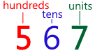
You may recall being taught how decimal numbers work in terms of place value. We say that the rightmost digits is the 'units' digits, the next one left is the 'tens' digit, the next is the 'hundreds' digit, and so on. What this actually meant is, the number is 100 × the value in the 'hundreds' digit, plus 10 × the value in the 'tens' digit, plus 1 × the value in the units digit.
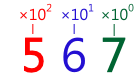
More mathematically, we can now spot the pattern and say that the rightmost digit is the 100=1s digit, the next left is the 101=10s digit, the next is 102=100s digit, and so on. We have all agreed on the system that 0 is the lowest digit, 1 is the next and so on. But what if we used a different number instead of 10 in these powers? Hexadecimal is just the system in which we use 16 instead.
The mathematics to the right shows that the number 567 in decimal is equivalent to the number 237 in hexadecimal. Often when we need to be clear about what system we're using to write numbers in we put 10 for decimal and 16 for hexadecimal. Since it's difficult to write small numbers in assembly code, we use 0x instead to represent a number in hexadecimal notation. So 0x237 means 23716.
So where do a,b,c,d,e and f come in? Well, in order to be able to write every number in hexadecimal, we need extra digits. For example 916 = 9×160 = 910, but 1016 = 1×161 + 1×160 = 1610. So if we just used 0,1,2,3,4,5,6,7,8 and 9 we would not be able to write 1010, 1110, 1210, 1310, 1410, 1510. So we introduce 6 new digits such that a16 = 1010, b16 = 1110, c16 = 1210, d16 = 1310, e16 = 1410, f16 = 1510
So, we now have another system for writing numbers. But why did we bother? Well, it turns out that since computers always work in binary, hexadecimal notation is very useful because every hexadecimal digit is exactly four binary digits long. This has the nice side effect that a lot of computer numbers are round numbers in hexadecimal, even though they're not in decimal. For example, in the assembly code just above I used the number 2020000016. If I had chose to write this in decimal it would have been 53896806410, which is much less memorable.
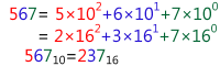
To convert numbers from decimal to hexadecimal I find the following method easiest:
- Start with the decimal number, say 567.
- Divide by 16 and calculate the remainder. For example 567 ÷ 16 = 35 remainder 7.
- The remainder is the last digit of the answer in hexadecimal, in the example this is 7.
- Repeat steps 2 and 3 again with the result of the last division until the result is 0. For example 35 ÷ 16 = 2 remainder 3, so 3 is the next digit of the answer. 2 ÷ 16 = 0 remainder 2, so 2 is the next digit of the answer.
- Once the result of the division is 0, you can stop. The answer is just the remainders in the reverse order to which you got them, so 56710 = 23716.
To convert hexadecimal numbers back to decimal, it is easiest to expand out the number, so 23716 = 2×162 + 3×161 +7 ×160 = 2×256 + 3×16 + 7×1 = 512 + 48 + 7 = 567.
So our first command is to put the number 2020000016 into r0. That doesn't sound like it would be much use, but it is. In computers, there are an awful lot of chunks of memory and devices. In order to access them all, we give each one an address. Much like a postal address or a web address this is just a means of identifying the location of the device or chunks of memory we want. Addresses in computers are just numbers, and so the number 2020000016 happens to be the address of the GPIO controller. This is just a design decision taken by the manufacturers, they could have used any other address (providing it didn't conflict with anything else). I know this address only because I looked it up in a manual[3], there is no particular system to the addresses (other than that they are all large round numbers in hexadecimal).
4 Enabling Output
Having read the manual, I know we're going to need to send two messages to the GPIO controller. We need to talk its language, but if we do, it will obligingly do what we want and turn on the OK LED. Fortunately, it is such a simple chip, that it only needs a few numbers in order to understand what to do.
mov r1,#1
lsl r1,#18
str r1,[r0,#4]
mov reg,#val puts the number val into the register named reg.
lsl reg,#val shifts the binary representation of the number in reg by val places to the left.
str reg,[dest,#val] stores the number in reg at the address given by dest + val.
These commands enable output to the 16th GPIO pin. First we get a necessary value in r1, then send it to the GPIO controller. Since the first two instructions are just trying to get a value into r1, we could use another ldr command as before, but it will be useful to us later to be able to set any given GPIO pin, so it is better to deduce the value from a formula than write it straight in. The OK LED is wired to the 16th GPIO pin, and so we need to send a command to enable the 16th pin.
The value in r1 is needed to enable the LED pin. The first line puts the number 110 into r1. The mov command is faster than the ldr command, because it does not involve a memory interaction, whereas ldr loads the value we want to put into the register from memory. However, mov can only be used to load certain values[4]. In ARM assembly code, almost every instruction begins with a three letter code. This is called the mnemonic, and is supposed to hint at what the operation does. mov is short for move and ldr is short for load register. mov moves the second argument #1 into the first r1. In general, # must be used to denote numbers, but we have already seen a counterexample to this.
The second instruction is lsl or logical shift left. This means shift the binary representation for the first argument left by the second argument. In this case this will shift the binary representation of 110 (which is 12) left by 18 places (making it 10000000000000000002=26214410).
If you are unfamiliar with binary, expand the box below:
Just like hexadecimal binary is another way of writing numbers. In binary we only have 2 digits, 0 and 1. This is useful for computers because we can implement this in a circuit by saying that electricity flowing through the circuit means 1, and not means 0. This is how computers actually work and do maths. Despite only having 2 digits binary can still be used to represent every number, it just takes a lot longer.
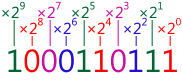
The image shows the binary representation of the number 56710 which is 10001101112. We use 2 to denote numbers written in binary.
One of the quirks of binary that we make heavy use of in assembly code is the ease by which numbers can be multiplied or divided by powers of 2 (e.g. 1,2,4,8,16). Normally multiplications and divisions are tricky operations, however these special cases are very easy, and so are very important.
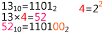
Shifting a binary number left by n places is the same as multiplying the number by 2n. So, if we want to multiply by 4, we just shift the number left 2 places. If we want to multiply by 256 we could shift it left by 8 places. If we wanted to multiply by a number like 12, we could instead multiply it by 8, then separately by 4 and add the results (N × 12 = N × (8 + 4) = N × 8 + N × 4).
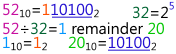
Shifting a binary number right by n places is the same as dividing the number by 2n. The remainder of the division is the bits that were lost when shifted right. Unfortunately dividing by a binary number that is not an exact power of 2 is very difficult, and will be covered in Lesson 9: Screen04.
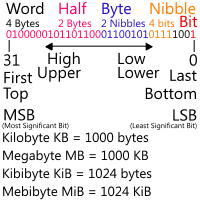
This diagram shows common terminology used with binary. A bit is a single binary digit. A nibble is 4 binary bits. A byte is 2 nibbles, or 8 bits. A half is half the size of a word, 2 bytes in this case. A word refers to the size of the registers on a processor, and so on the Raspberry Pi this is 4 bytes. The convention is to number the most significant bit of a word 31, and the least significant bit as 0. The top, or high bits refer to the most significant bits, and the low or bottom bits refer to the least significant. A kilobyte (KB) is 1000 bytes, a megabyte is 1000 KB. There is some confusion as to whether this should be 1000 or 1024 (a round number in binary). As such, the new international standard is that a KB is 1000 bytes, and a Kibibyte (KiB) is 1024 bytes. A Kb is 1000 bits, and a Kib is 1024 bits.
The Raspberry Pi is little endian by default, meaning that loading a byte from an address you just wrote a word to will load the lowest byte of the word.
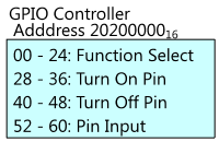
Once again, I only know that we need this value from reading the manual[3]. The manual says that there is a set of 24 bytes in the GPIO controller, which determine the settings of the GPIO pin. The first 4 relate to the first 10 GPIO pins, the second 4 relate to the next 10 and so on. There are 54 GPIO pins, so we need 6 sets of 4 bytes, which is 24 bytes in total. Within each 4 byte section, every 3 bits relates to a particular GPIO pin. Since we want the 16th GPIO pin, we need the second set of 4 bytes because we're dealing with pins 10-19, and we need the 6th set of 3 bits, which is where the number 18 (6×3) comes from in the code above.
Finally the str 'store register' command stores the value in the first argument, r1 into the address computed from the expression afterwards. The expression can be a register, in this case r0, which we know to be the GPIO controller address, and another value to add to it, in this case #4. This means we add 4 to the GPIO controller address and write the value in r1 to that location. This happens to be the location of the second set of 4 bytes that I mentioned before, and so we send our first message to the GPIO controller, telling it to ready the 16th GPIO pin for output.
5 A Sign Of Life
Now that the LED is ready to turn on, we need to actually turn it on. This means sending a message to the GPIO controller to turn pin 16 off. Yes, turn it off. The chip manufacturers decided it made more sense[5] to have the LED turn on when the GPIO pin is off. Hardware engineers often seem to take these sorts of decisions, seemingly just to keep OS Developers on their toes. Consider yourself warned.
mov r1,#1
lsl r1,#16
str r1,[r0,#40]
Hopefully you should recognise all of the above commands, if not their values. The first puts a 1 into r1 as before. The second shifts the binary representation of this 1 left by 16 places. Since we want to turn pin 16 off, we need to have a 1 in the 16th bit of this next message (other values would work for other pins). Finally we write it out to the address which is 4010 added to the GPIO controller address, which happens to be the address to write to turn a pin off (28 would turn the pin on).
6 Happily Ever After
It might be tempting to finish now, but unfortunately the processor doesn't know we're done. In actuality, the processor never will stop. As long as it has power, it continues working. Thus, we need to give it a task to do forever more, or the Raspberry Pi will crash (not much of a problem in this example, the light is already on).
loop$:
b loop$
name: labels the next line name.
b label causes the next line to be executed to be label.
The first line here is not a command, but a label. It names the next line loop$. This means we can now refer to the line by name. This is called a label. Labels get discarded when the code is turned into binary, but they're useful for our benefit for referring to lines by name, not number (address). By convention we use a $ for labels which are only important to the code in this block of code, to let others know they're not important to the overall program. The b (branch) command causes the next line to be executed to be the one at the label specified, rather than the one after it. Therefore, the next line to be executed will be this b, which will cause it to be executed again, and so on forever. Thus the processor is stuck in a nice infinite loop until it is switched off safely.
The new line at the end of the block is intentional. The GNU toolchain expects all assembly code files to end in an empty line, so that it is sure you were really finished, and the file hasn't been cut off. If you don't put one, you get an annoying warning when the assembler runs.
7 Pi Time
So we've written the code, now to get it onto the pi. Open a terminal on your computer and change the current working directory to the parent directory of the source directory. Type make and then press enter. If any errors occur, please refer to the troubleshooting section. If not, you will have generated three files. kernel.img is the compiled image of your operating system. kernel.list is a listing of the assembly code you wrote, as it was actually generated. This is useful to check that things were generated correctly in future. The kernel.map file contains a map of where all the labels ended up, which can be useful for chasing around values.
To install your operating system, first of all get a Raspberry PI SD card which has an operating system installed already. If you browse the files in the SD card, you should see one called kernel.img. Rename this file to something else, such as kernel_linux.img. Then, copy the file kernel.img that make generated onto the SD Card. You've just replaced the existing operating system with your own. To switch back, simply delete your kernel.img file, and rename the other one back to kernel.img. I find it is always helpful to keep a backup of you original Raspberry Pi operating system, in case you need it again.
Put the SD card into a Raspberry Pi and turn it on. The OK LED should turn on. If not please see the troubleshooting page. If so, congratulations, you just wrote your first operating system. See Lesson 2: OK02 for a guide to making the LED flash on and off.
- [1]^ OK, I'm lying it tells the linker, which is another program used to link several assembled files together. It doesn't really matter.
- [2]^ Clearly they're important to you. Since the GNU toolchain is mainly used for creating programs, it expects there to be an entry point labelled _start. As we're making an operating system, the _start is always whatever comes first, which we set up with the .section .init command. However, if we don't say where the entry point is, the toolchain gets upset. Thus, the first line says that we are going to define a symbol called _start for all to see (globally), and the second line says to make the symbol _start the address of the next line. We will come onto addresses shortly.
- [3]^^ This tutorial is designed to spare you the pain of reading it, but, if you must, it can be found here SoC-Peripherals.pdf. For added confusion, the manual uses a different addressing system. An address listed as 0x7E200000 would be 0x20200000 in our OS.
- [4]^ Only values which have a binary representation which only has 1s in the first 8 bits of the representation. In other words, 8 1s or 0s followed by only 0s.
- [5]^ A hardware
engineer was kind enough to explain this to me as follows:
The reason is that modern chips are made of a technology called CMOS, which stands for Complementary Metal Oxide Semiconductor. The Complementary part means each signal is connected to two transistors, one made of material called N-type semiconductor which is used to pull it to a low voltage and another made of P-type material to pull it to a high voltage. Only one transistor of the pair turns on at any time, otherwise we'd get a short circuit. P-type isn't as conductive as N-type, which means the P-type transistor has to be about 3 times as big to provide the same current. This is why LEDs are often wired to turn on by pulling them low, because the N-type is stronger at pulling low than the P-type is in pulling high.
There's another reason. Back in the 1970s chips were made out of entirely out of N-type material ('NMOS'), with the P-type replaced by a resistor. That means that when a signal is pulled low the chip is consuming power (and getting hot) even while it isn't doing anything. Your phone getting hot and flattening the battery when it's in your pocket doing nothing wouldn't be good. So signals were designed to be 'active low' so that they're high when inactive and so don't take any power. Even though we don't use NMOS any more, it's still often quicker to pull a signal low with the N-type than to pull it high with the P-type. Often a signal that's 'active low' is marked with a bar over the top of the name, or written as SIGNAL_n or /SIGNAL. But it can still be confusing, even for hardware engineers!
Spot a mistake? You can help improve this tutorial on GitHub.

Baking Pi: Operating Systems Development by Alex Chadwick is licensed under a Creative Commons Attribution-ShareAlike 3.0 Unported License.
Based on contributions at https://github.com/chadderz121/bakingpi-www.