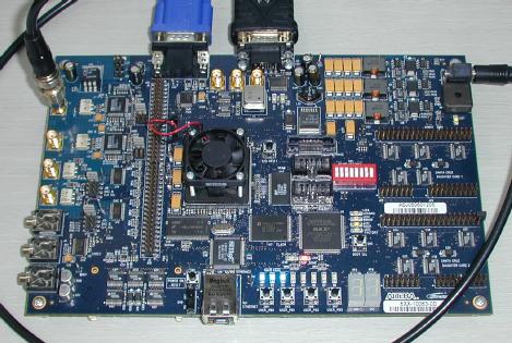
The COVISP project developed a low-cost system for capturing, visualizing and analyzing compromising video signals. The hardware platform initially chosen was an off-the-shelf FPGA evaluation board, Altera’s DSP Development Kit, Stratix II Edition (DK-DSP-2S60N). This board is then combined with an antenna, radio receiver (wideband VHF/UHF to IF downconverter), VGA display and optionally a PC to form a complete demonstration system for high-quality real-time display of compromising video emanations from both CRT and flat-panel displays.
I receive occasionally purchasing enquiries for a COVISP system. The two existing prototypes are not available for sale, one is actively being used in our lab and the other is with the original project sponsor.
Unfortunately, I can't immediately supply more right now: the Altera DK-DSP-2S60N board that we initially used as a hardware platform has been discontinued and is no longer available from the distributors (Digikey), so unless you find somewhere a functioning second-hand version of this board, you will have to wait until we have selected a new hardware platform and ported the circuit to it. (This is not trivial: successor boards replaced the analog VGA output with a DVI one, but the original COVISP clock synthesis circuit was not designed to supply a pixel-clock signal that meets DVI standard jitter requirements.)
Note that once I can supply COVISP boards again, you will still need in addition: a suitable antenna, a receiver, a VGA display, a controlling laptop (optional, with USB<->RS232 adapter). Your receiver should have an IF output with at least 10 MHz bandwidth (better 40 MHz or more) that can amplify the desired signal to at least a few tens of millivolts, see datasheet for details. As receivers, we have used so far available lab measurement receivers or spectrum analyzers.
The FPGA is programmed in the currently implemented version to fulfil the following functions:
Ideas for possible extensions include:
Project status: The initial project was completed in March 2006 by delivering a prototype and providing user training to the initial project sponsor (GBS) for a demonstration at CeBIT 2006. Currently planned work includes improving the prototype's firmware and user interface. Adding an on-screen menu and reassigning the on-board buttons accordingly should make the board easier to use without a laptop connected via RS-232. We are also exploring the possibility of a follow-on project using an SDR platform (e.g., Ettus USRP B200, Per Vices Noctar, BladeRF, Microsoft SORA).
Documents:
The Altera DSP Development Kit features two AD9433BSQ analog-to-digital converters with 12-bit linear resolution and up to 125 MHz sampling frequency. They are AC coupled via pairs of 1:1 balun transformers to on-board SMA connectors. These inputs accept voltages in the range −1..+1 V and have 50 ohm impedance (0 dBFS = 0.7 Vrms = 117 dBµV = 10 dBm). The input resolution at 12-bit resolution is 0.5 mV (−62 dBm).
These inputs are designed to be connected to the IF output of a radio receiver. The transformers attenuate frequencies below about 1 MHz, so these inputs are less suitable for monitoring the baseband output of a demodulator. Instead, the AM demodulation will have to be done digitally inside the FPGA. This has the advantage that we will have software control over the exact IF bandwidth and demodulation technique (AM, QAM, etc.), and can even add digital notch filter to suppress narrowband interference sources within the IF bandwidth. We will only need one of the two inputs, to acquire the IF video signal. (The second input remains free for other applications. One possible application for it might be an extension for phase-locking the averager using a low/medium frequency receiver that picks up CRT deflection-coil signals. Another possibility is to interleave both ADCs to double the sampling rate to 250 MHz. A third application would be to display real-time correlation between two signals (red/black).)
With a sampling frequency of 125 MHz, we can acquire spectral content in roughly the 1..60 MHz range without any aliasing. This fits well with the 30 MHz IF filter center frequency that our Dynamic Sciences R1250 receiver uses (only for bandwidths up to 20 MHz).
If the ADCs are operated without the 55 MHz low-pass anti-aliasing filter that comes with the board, they can even detect signal frequencies up to 750 MHz. This means, it should also be possible to directly handle IF signals up to about 700 MHz, because they can be downconverted into the 0..60 MHz range through aliasing.
There is also the option of not using any superhet receiver at all, but to use instead simply a small collection of (tunable) bandpass antenna amplifiers for the bands of interest. This low-cost option may be particularly feasible in demonstration setups, where the target frequency range is known well in advance.
Frequency range: The wideband-impulse video signals that we are interested in are typically found with a usable signal-to-noise ratio in the 200..800 MHz range, predominantly in the lower half of that interval. So the receiver should cover the upper VHF and lower UHF frequency range. 1..3 GHz might also be of interest for digital video signals.
IF bandwidth: Practically useful receiver bandwidths are in the 20..50 MHz range; anything below blurs realistic font sizes too much, anything above is beyond what the Altera DSP board could handle.
IF output: The receiver should have an intermediate-frequency output connecter (e.g., 50 ohm BNC).
IF frequency: The center frequency of its IF band should ideally be the 20..40 MHz range, although we might be able to handle (via aliasing) anything up to 700 MHz.
Sensitivity: The background noise encountered in quieter parts of the 200..800 MHz spectrum is about 20..50 dBµV/m at 20..50 MHz bandwidth. With an antenna factor of 20 dB (log-periodic UHF antenna), this translates into receiver input voltages in the 0..30 dBµV (−107..−77 dBm) range.
IF level and gain: The receiver's IF output should ideally be able to deliver signals at up to 10 dBm (2 Vpp). Therefore, the receiver's overall pre-detection gain should ideally be adjustable over roughly 87..117 dB, if we want to drive the ADC near 0 dBFS to use all 12-bits resolution. Otherwise, since the ADC can still detect signals at −60 dBFS, we could still see something with IF receiver gains as low as 30 dB. (Warning: some spectrum analyzers feature an IF output with 0 dB RF gain, which is not useful. We need at least 30 dB gain in the RF front-end before we can add more gain with an external IF amplifier (e.g., ZFL-500LN) if necessary, otherwise the signal will end up very noisy.)
Linearity and noise figure: The data sheet of the R1250 receiver used so far claims a noise figure of 10 dB and characterizes the linearity of its input amplifier by giving the intermodulation ratio for two tones in the RF passband as 60 dB (2nd order) and 75 dB (3rd order), respectively. (I can't offer minimum requirements for these performance figures yet, but for isolating very weak signals in the vicinity of strong transmitters, high linearity and thus low intermodulation products are obviously beneficial.)
Demodulator: No analog demodulator is necessary, we do all that on the DSP board from the IF output.
I have used so far log-periodic EMC measurement antennas designed for 200..1000 MHz. They work reasonably well, but have several disadvantages:
An alternative with even less directional gain would be a discone antenna.
Various signal-intelligence practitioners have mentioned log-conical spiral antennas as their preferred choice (left or right circular polarization), possibly because compromising emanations often have elliptical polarization.
If for a demonstration the exact frequency is known in advance, a Yagi antenna could be built, which would outperform the log-periodic antenna in both phase stability and gain.
Another option would be an active antenna with built-in bandpass filter (e.g., 200..800 MHz). Its usability may depend on how strong other signals are in passband of the amplifier.
Also of interest would be power-line probes for frequencies in the 30..300 MHz range.
created 2005-12-08 – last modified 2007-04-27 – http://www.cl.cam.ac.uk/~mgk25/covisp/