In this practical, you'll create a project in Quartus II that will use
the ARM processor on the Excalibur chip to generate a series of prime
numbers. This will allow you to try out your assembly programming skills and
gain experience of using a remote debugger. The ARM is part of the Excalibur
Embedded Stripe - this is a hard-wired part of the board. It contains the ARM,
Dual-Ported RAM, SRAM, and a serial port.
In order for Quartus to understand that we want to use the ARM in
the stripe, a MegaFunction has to be defined. This is a
computer-generated Verilog module that the compiler knows is actually
the ARM processor. A small piece of Verilog then joins up the pins
that are needed, in a similar manner to any other Verilog Module.
You might want to read through the ARM
Quick Reference, the copy of the the instruction set reference
provided, and maybe also look back through lecture four of the Computer Design
notes on the ARM Procedure Calling Standard. One or two of the instructions
listed on the instruction quick reference may not work if there is something in
the Greek-looking symbol column, so it is an idea to check (the ARM922T is an
ARMv4 architecture).
|
First create a new directory in your file space, and download the
following files into it:
- main.v - The Verilog file that links the
ARM to the Excalibur's pins
- main.s - Assembler code for the ARM
- serialio.s - Assembler library to
allow communication via the serial port. There is some documentation for each
function inside the file.
Open Quartus II from the Start menu, and select File |
New Project Wizard.... Enter the directory, the project name as
'primes' and the top-level entity as 'main'. On the next screen, add
'main.s', 'main.v', and 'serialio.s' to the project files, and set the rest of
the options as Lab 1 suggested. Now, go to the TCL Console and type 'source
excalibur_pins.tcl' as in the first Lab.
Now, the final part of setting up the project is creating the ARM
Stripe MegaFunction.
- Select Tools | MegaWizard Plug-In
Manager..., and choose Create a new MegaFunction
Variation.
- On the next screen, select ARM-Based Excalibur from
the list on the left, EXCALIBUR_ARM for the device family, Verilog
HDL for the type of output file, and for the output filename, your project directory\arm.v.
- On the next page, make sure the device is EPXA1, and its
Endianness is set to 'Little'. All the tickboxes apart from
UART should be unticked. Outputs and Inputs should be left
at their default values.
- On the next page, untick everything.
- On the page after, for external reference frequency, use 25
MHz. Bypass PLL1 should be ticked, with the two AHB frequencies at
their default values, and the tickbox for using an EEPROM should be
unticked.
- The next page is where you select your memory map. This is where in
the ARM's address space it is able to access the devices available to
it. Select 16K for SRAM0 and SRAM1, and set their addresses to
00000000 and 00004000 respectively. This means that
there are now two 16K blocks of SRAM available from address 0 to
7FFFh (the 'h' suffix means 'hexadecimal').
- DPRAM is dual-ported RAM and should be OFF for this practical,
and the registers should be left as they are.
- Click next, and then finish, and you should be able to
compile your project using the standard Compile button.
Unfortunately, you're not quite done yet, because Quartus II needs
telling that it should also compile main.s and create the files for
it.
- Go to Assignments | Settings...
- Select Software build settings in the left-hand pane.
- Set Embedded processor architecture to ARM922T, and Software toolset to ADS Standard Tools. ADS stands for ARM Developer Suite.
- Set Byte order to Little endian.
- Set Output file format to .hex and the file name to "prime.hex".
- Under Programming file generation, select passive configuration and set the file name to "main.psof".
- Now, go to Software Build Settings | Linker in the left-hand pane, and set Link Type to Simple. Tick all three
boxes, and set them to "0". This tells the
Linker that it must fit everything into memory starting at address 0.
- You also need to ensure that main.s appears first in the linked image.
To do this add "-first main.o" to the command line arguments. If we
had been running from FLASH or non-writable memory, we probably would
have set these up differently.
- Now go to Software Build Settings | Toolset directories in the left-hand pane.
- Finally, select ADS Standard Tools from the list. The toolset directory should be correctly set. If toolset directory is not set, set it to "y:\armds1.2\bin" and click change.
- Click on OK and click Build on the toolbar to build the program.
After this is done, you can upload to the FPGA. Go to Tools |
Programmer and click the button marked 'Auto Detect'. This will detect all
devices on the JTAG chain - there should be 2 of them (if not, change the
jumper on the EPXA1 board marked JSELECT to the 2-3 position and try again).
Right-click on the one marked EPXA1 and choose 'Change File'. Select
main.sof, and tick the 'Program/Configure' box.
When you click Start Programming the image will be uploaded
to the FPGA, and a message will be output on the Serial port. To see
this, plug your serial cable into the connector on the short edge of
the EPXA1 board (the one that protrudes through a hole in the box),
and load TeraTerm from the start menu. Set it up to connect via
the serial port your cable is plugged into at the computer (the top one is COM2 and the bottom one is COM1),
and then go to Setup | Serial port... and set it to 38400 baud,
8 data bits, no parity, 1 stop bit, and no flow control. After
uploading the file, you should see the following:
**************************************
*  ECAD + Arch Lab 4 - Prime Number  *
*              Generator             *
**************************************

Finished! :)
|
The ARM Debugger (AXD) is provided for remote debugging via the
MasterBlaster interface. The debugger allows you to step through
your code whilst monitoring registers and memory contents.
AXD should be in the usual place in the Start menu.
When AXD loads, it may ask you to choose a target. The target is
the hardware or emulator on which your code is running. In this case
you need to select Altera-RDI to connect to the EPXA1 board.
If this does not appear, click on the Add button, and open the
file called
Y:\Quartus40\quartus\bin\Altera-RDI.dll.
If the Choose Target window does not
appear, select Options | Configure Target. If AXD fails to
connect to the EPXA1, try choosing the target again.
The debugger allows you to watch your program being executed
instruction by instruction. You can see also the contents of the
registers and memory changing. In order to see all of these you will
need to open a sub-window for each:
- To see the contents of the registers, select Processor Views |
Registers and expand the "Current" sub-tree to create a small window
showing the current register values.
- To see the contents of the memory, select Processor Views |
Memory. Set the Start address to 0, as this is where your
program will reside.
- To see the instructions being executed, select Processor
Views | Disassembly. Note that there is a blue arrow pointing to
one instruction. This represents the current execution point.
If you have just loaded the sample code into the board, you should
find that the processor has reached the infinite loop (at address
0x18). Now set the PC to 00 (Right click in the Disassembly window
and select Set PC...).
- To execute the program hit F5 or click the
 icon.
icon.
- To step through the program, press F8 (or click the
 icon) a few times. Try this after setting the PC
back to 0. This will advance the blue arrow and execute the next
assembler instruction, following subroutine calls. Notice how the
register values and memory change. icon) a few times. Try this after setting the PC
back to 0. This will advance the blue arrow and execute the next
assembler instruction, following subroutine calls. Notice how the
register values and memory change.
- When you get to a bl instruction, pressing F8 again will
step you into a subroutine. Using F10 (or clicking
 )
instead, will advance over the instructions one at a time, but will not 'step'
into the subroutine. )
instead, will advance over the instructions one at a time, but will not 'step'
into the subroutine.
- Running an entire program like this could get very tedious, so it
will be useful to set breakpoints. These allow the program to
run freely until the processor reaches a specific instruction, at
which point it stops and the registers and memory are displayed. To
set a breakpoint, place the cursor by the instruction and press F9 (or
click on
 , or double-click the instruction in the
disassembly). Now press F5 (); the program will run
until it reaches the breakpoint. , or double-click the instruction in the
disassembly). Now press F5 (); the program will run
until it reaches the breakpoint.
- The Run To Cursor button (F7 or
 )
does exactly what it says... )
does exactly what it says...
In summary, "step in" will do one instruction at a time; "step
over" will do one instruction or subroutine at a time; and breakpoints
halt the run whenever they are hit. They provide different
granularities of control over debugging.
|
|
|
|
|
Task: Prime Number Generator
|
| |
|
|
|
|
|
|
|
|
Write a program to produce a table of the first 1000 primes in
hexadecimal. The table should be neatly printed on the console and
should include an index number by each prime. You might like to use
one of the following two methods.
Repeated Division Method
One method for determining if N is prime is to try dividing it by
primes less than sqrt(N). Note that the ARM does not have
instructions that perform division and remainder operations. However,
you can use the code from the Computer Design notes. Note that it
expects r0 to contain the value to be divided, and r1 to contain the
dividend. The result is left in r1, and remainder in r0, but r2 and r3
are corrupted in the process. It might also be useful to know that in
the event you divide something by 0, it dies horribly and just gets
stuck in an endless loop.
DivStart				; enter with numbers in r0 and r1
	mov	r2,#1			; bit to control the division
Div1	cmp	r1,#0x80000000		; shift r1 left until top bit set...
	cmpcc	r1,r0			; ...or r1>r0
	movcc	r1,r1,LSL#1		; shift r1 left if require
	movcc	r2,r2,LSL#1		; shift r2 left if r1 is shifted
	bcc	Div1			; repeat whilst more shifting required
	mov	r3,#0			; zero r3
Div2	cmp	r0,r1			; test for possible subtraction
	subcs	r0,r0,r1		; subtract if r0>r1
	addcs	r3,r3,r2		; put relevant bit into result
	movs	r2,r2,LSR#1		; shift control bit
	movne	r1,r1,LSR#1		; halve unless finished
	bne	Div2			; loop if there is more to do
					; divide result in r3
					; remainder in r0
	mov	r1,r3			; divide result (r0/r1) now in r1
	mov	r15,r14			; return from subroutine
Sieve of Eratosthenes
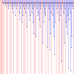 Alternatively you could
use the Sieve of Eratosthenes. To the right is an incomprehensible
diagram showing this algorithm working. From left to right are
numbers, and from top to bottom are steps of computation. In the first
step, every 2nd number is marked as non-prime, since they are
multiples of 2. The next prime is found (3) and every multiple of 3 is
ticked off, and so on. This leaves only prime numbers unmarked (which
are shown in red).
For the sieve, you need some memory that can be used to store the
table of values. If you insert the following code at the end of the
file (just before END), the assembler will allocate 1024 bytes
of memory. Due to the ARM only being able to directly access 4k of
memory relative to the program counter, and the use of the
LDR r#,=... macro (which in some cases allocates memory to store
constants too), allocating more than around 2000 bytes may cause the
assembler to complain.
	ALIGN			; ensure allocated memory is word aligned
primes_table	%	1024	; e.g. allocated 1024 bytes
				; to load the address of this into a register, use:
				; ldr r0,=primes_table
It is recommended that you use entire bytes (and use the
ldrb and strb instructions) to store values for the
Sieve of Eratosthenes.
Data Output
Use the UART_TXD_DECIMAL routine to output an index number and the
UART_TXD_HEX routine to output the prime. These take the value in r0 and
output it to the serial port (r1,r2 and r3 are changed in the
process). To output a space character to separate the numbers, use the
following code (32 is the character code for space):
	mov	r0,#32
	bl	UART_TXD
Similarly, to end the line, output a line-feed character and a newline:
	mov	r0,#13
	bl	UART_TXD
	mov	r0,#10
	bl	UART_TXD
To output a single character, you can either use the ASCII code as in the examples above, or you can use the character itself:
	mov	r0, 'a'
	bl	UART_TXD
Questions
- What are the first ten primes in hexadecimal?
- What is the 1000th prime in hexadecimal?
- What is the computational complexity of your implementation?
Ticking Criteria
Ticking procedure
- Show your work to one of the demonstrators (on screen or
paper). They will award you with a tick if the work is up to
standard.
- Print out your final work and add it to your portfolio to be
submitted as instructed in the Head of Department notice.
|