|
|
|||||
| Computer Laboratory
Datasheets |
||
| Computer Laboratory > Course material 2004-05 > ECAD + Architecture Main Page > Datasheets |
|
This page contains datasheets and information that you may need during ECAD practicals.
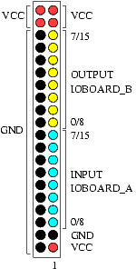 This is the pinout for the 40 pin headers on the IO Board. Pin 1 is the pin nearest the Excalibur board, and furthest from the yellow IC on the top (it may be marked with an 'H'). Header 1 is nearest the Excalibur board, and uses the Verilog pins IOBOARD_A[0:7] and IOBOARD_B[0:7]. Header 2 uses IOBOARD_A[8:15] and IOBOARD_B[8:15].
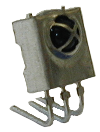
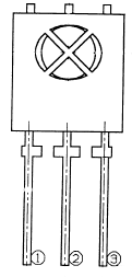
This is a PIC-26043SM Farnell order code 139-877. It takes 5V on pin 3, GND on pin 2 and gives an open collector output on pin 1. The output is also inverted, and so is pulled to ground (sinks current) when a IR signal is received. It thus needs a 470 Ohm pull-up resistor to 5V to be able to interface it to TTL logic.
General Information Signal Format Signal Format (Local Copy)
ARM922T DataSheet ARM Instruction Quick Reference ARM Tips
The clock display is an 88:88 format, common cathode device. The part number for these is HDSP-B03E. DataSheet |