
ECAD and Architecture Practical Classes
Qsys & Mandelbrot set on the Nios-II
Introduction
In this section you will build a Qsys project containing a Nios-II processor and run a program which will plot the Mandelbrot set on the LCD. This Qsys setup and program will be modified later in the lab to make use of many instances of the TTC processor introduced in the last lab and in lectures.
Starting a new project
Start a new project using the same procedure as for the first lab, calling it ecad_lab_2 this time.
Starting Qsys
Start Qsys by going to Tools | Qsys. On the left are a list of components. Along the top are a list of tabs.
Qsys relies on components implementing one or more interfaces made up of signals. The two most important interface standards supported by Qsys are Avalon-MM and Avalon-ST. These are standards for components interacting in a memory mapped (bidirectional, addressed) and streaming (unidirectional, optionally has channels) manner respectively. Qsys will connect components via the "Qsys interconnect" which refers to glue logic which Qsys will insert to make sure standards complient components can interact. This includes address mux/demux (eg to connect an Avalon-MM master to multiple slaves), insertion of adapters (the standards allow for flexibility in which signals are used and how they're used), arbitration (to connect multiple Avalon-MM masters to one slave) and so on. You can find many of the components implementing this glue logic under the "Merlin Components" menu, but we usually let the tool hide this detail. Towards the end of this lab an alternative way of connecting many components will be persued in an attempt to minimise resource usage due to routing logic.
Give your system a name by clicking File | Save, typing mandelbrot.qsys then clicking Save.
Adding components
PLL
The design being built has different components which require different frequency clocks. In particular, the video subsystem needs to run at 40Mhz, the frequency of the LCD's pixel clock, while the rest of the system should be able to run at 100Mhz. The SDRAM will also be run from a 100Mhz clock, but with a phase adjustment to account for the distance between the FPGA and the SDRAM.
A PLL is a Phase Locked-Loop, which can derive clocks using a combination of analog and digital circuitry. The FPGA has a number of these circuits as hard blocks (i.e. they are not conventional reconfigurable hardware) which can be configured via the MegaFunction Wizard in Quartus or as a library component in Qsys.
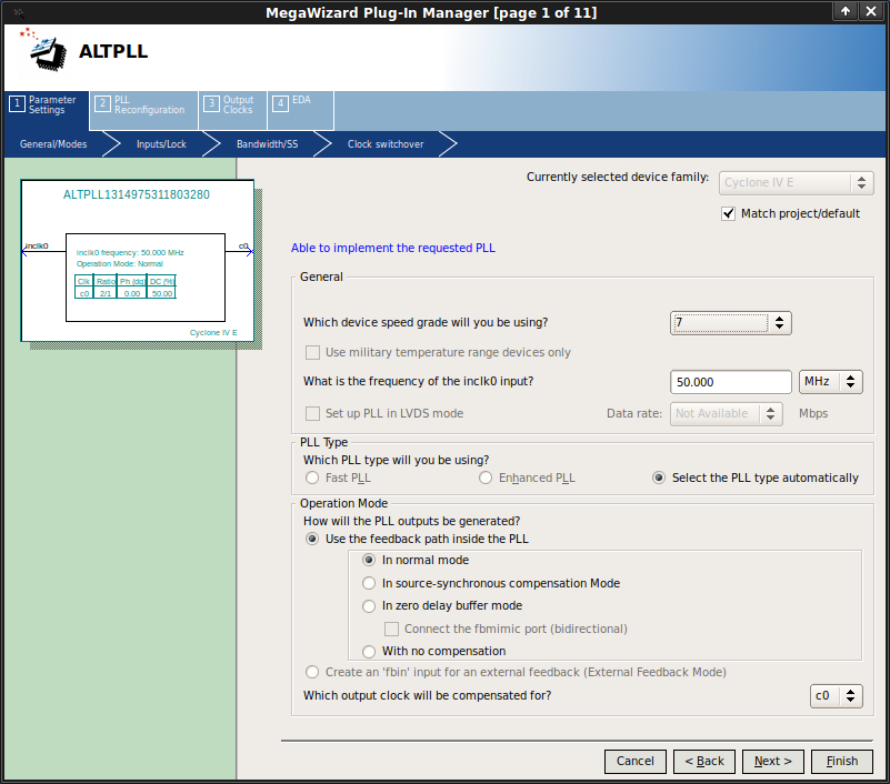


Add a PLL by double clicking PLL | Avalon ALTPLL and then configure:
- Set device speed grade to 7 and the input frequency to 50Mhz then click Next >.
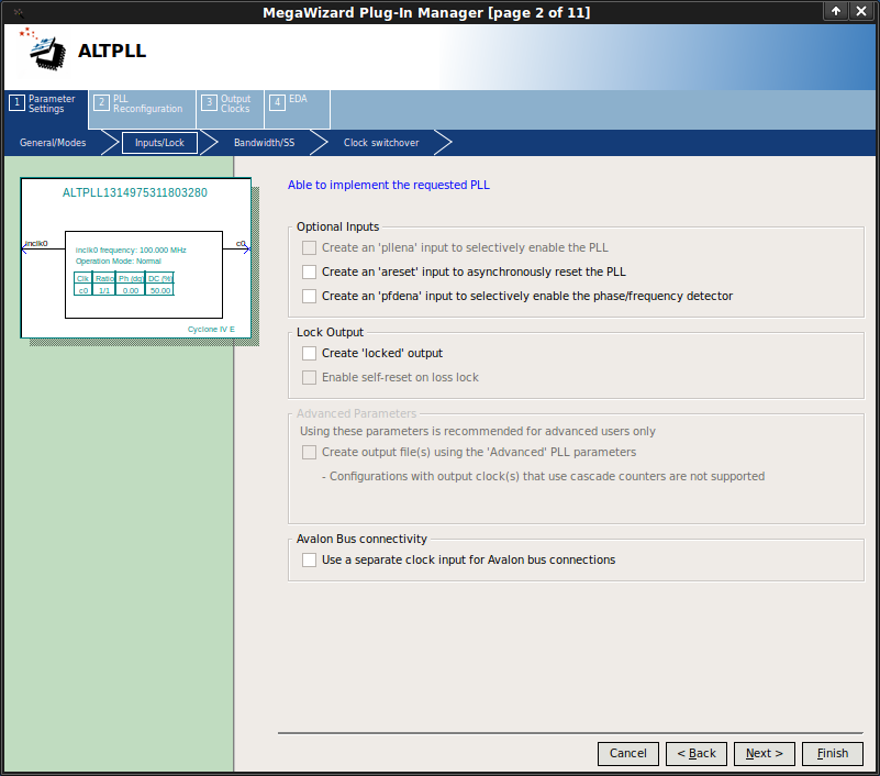
- On this page untick the boxes for the areset input and the locked output as these are unneccesary for our purposes. Now click Next > until you reach page 6.
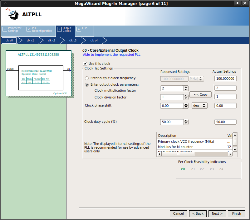
- Clock c0 will be the main system clock. Set the Clock muliplication factor to 2 and click Next >.
- Clock c1 will be the external SDRAM clock (not the clock for the SDRAM interface on the FPGA). Tick Use this clock and set the Clock muliplication factor to 2 and Clock phase shift to -3ns (N.B. change units from deg to ns) and click Next >. The phase shift adjusts for differences in on-FPGA and off-FPGA timing
- Clock c2 will be the video clock. Tick Use this clock and set the Clock muliplication factor to 4 and the Clock division factor to 5 to provide a 40MHz clock. Finally, click Finish twice.
Nios-II
The Nios-II is a 32-bit RISC soft-core microprocessor architecture designed by Altera for use with their FPGAs. It is configurable in that many features are optional and some are configurable, eg the number of pipeline stages. Since this architecture has a mature C compiler, the main program will be run on this processor.
Add an Nios-II processor by double clicking Processors | Nios II Processor. Set Reset vector memory and Exception vector memory to Absolute then click Finish.
JTAG UART
Add an JTAG UART by double clicking Interface Protocols | Serial | JTAG UART and clicking Finish.
Timer
Add an timer by double clicking Peripherals | Microcontroller Peripherals | Interval Timer and clicking Finish.
RAM
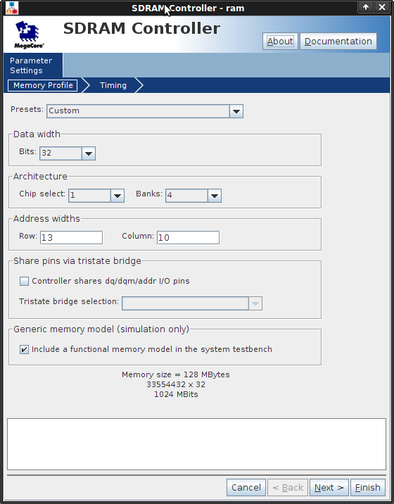
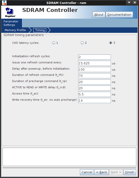
While the FPGA chip itself has distributed memory blocks of SRAM woven into its array of logic elements, this memory is limited in size and may be being used for other parts of your design. The DE2-115 also has two external SDRAM chips making up 128MiB of dynamic memory (DRAM), which is suitable for use as a main memory for the Nios-II. DRAM needs to be constantly refreshed and is sensitive to timing. Therefore, to deal with these issues and present the Nios-II with a standard Avalon-MM slave interface, we will add an SDRAM controller.
Add an SDRAM controller by double clicking Memories and Memory Controllers | SDRAM | SDRAM Controller in the components panel and setting it up as shown in the screen shots above.
Video Framebuffer
We have created a video framebuffer Qsys subsystem based on an Altera reference design. This uses a direct memory access (DMA) engine to repeatedly read out memory and sends the pixel data through some timing and data-format adapters out to the LCD.
Download the video subsystem Qsys project, a component it requires and the associated Verilog to your project directory. In Qsys, press F5 to refresh the system. You should now be able to add the component by double clicking System | video in the Component Library then clicking Finish.
Touchscreen
Download the touchscreen subsystem here. Add touchscreen.qsys to your project. In Qsys, press F5 to refresh the system. Add the component by double clicking System | touchpad in the Component Library then clicking Finish.
Connecting components
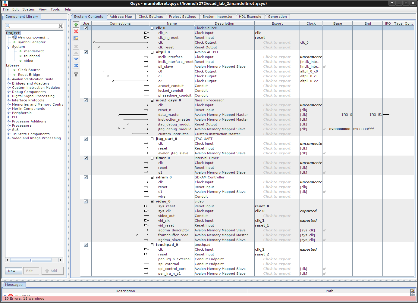
At this point if you have followed the instructions correctly your System Contents should look similar to that pictured on the right.
Under the System Contents tab, a patch bay is displayed in the connection column. Each interface of each component has an associated line. Where two compatible interfaces' lines cross, a circle will appear if you hover your mouse over the intersection. When this circle is empty, the interfaces are not connected, when it is filled they are. Clicking the circle toggles state. Signals can also be exported in which case they are part of the interface of the module Qsys generates and therefore must be connected at instantiation.
Clocks/Resets
First rename the clocks (to something more meaningful) by double clicking an entry in the name Name column under the Clock Settings tab: the external clock should be named ext_clk, c0 should be named sys_clk; c1, sdram_clk; and c2, video_clk.
The PLL (altpll_0) needs its inclk clock input connected to ext_clk. All other components except video should be clocked according to sys_clk:
- nios2_qsys_0/clk to sys_clk
- jtag_uart_0/clk to sys_clk
- timer_0/clk to sys_clk
- sdram_0 (SDRAM controller) clk to sys_clk
- video_0/sys_clk to sys_clk
- touchpad_0/clk to sys_clk
- Video has two clocks: sys_clk connects to sys_clk and vid_clk connects to video_clk
- Video also has a vid_clk_out signal which needs to exported to the LCD panel to provide its HC_NCLK. Click on Click to Export in the Export column under the System Contents tab and leave the default name of video_0_vid_clk_out.
- sdram_clk aka c1 should be exported by clicking Click to export in the Export column under the System Contents tab and typing sdram_clk.
Resets can be handled automatically but first you'll need to remove any exported reset signals (in the Export column), e.g. for video_0 and touchpad_0. To connect the resets, click System | Create Global Reset Network.
Avalon-MM
Now we need to connect up the data and instruction memory interconnects:
- Click on the line in the system contents for the data_master under nios2_qsys_0.
- Now move the mouse to the connections area and click on the empty circle corresponding to the following connections (hovering confirms the connection that will be made):
- connection from nios2_qsys_0.data_master to altpll_0.pllslave
- data_master to jtag....
- data_master to timer....
- data_master to sdram_0
- data_master to sgdma_descriptor_mem
- data_master to sgdma_slave
- data_master to spi_control_port
- data_master to pen_irq_n_s1
- instruction master connects to sdram_0.s1
- framebuffer read to sdram_0.s1
Change the base of the SDRAM to 0x00000000 and click the padlock to lock it there. Now, click System | Assign Base Addresses. Qsys should assign addresses to everything apart from interfaces on the video and touchpad subsystems. This is a bug in Qsys. It's probably easiest to assign the video and touchpad Avalon-MM slaves addresses starting at 0x08000000 then rerun System | Assign Base Addresses for the rest of the system eg video.sgdma_descriptor/video.sgdma_slave/touchpad.spi_control_port/touchpad.pen_irq_n_s1 at 0x08000000/0x08001000/0x08001040/0x08001060 respectively.
Interrupts
To connect interrupts they must first be shown by right clicking anywhere in System Contents and clicking Filter | All interfaces. Now connect every Interrupt Sender interface to the Nios-II's Interrupt Receiver interface. Ensure the interrupt numbers are assigned correctly by clicking System | Assign Interrupt Numbers.
Exports
Apart from the clock input (aka ext_clk) and the sdram clock output (aka sdram_clk), the sdram, video and touchpad components all need to connect with signals which are external to the FPGA and therefore external to this system. They will be attached to top level inputs and outputs when the system is instantiated at the top level. To connect these signals, they must be exported.
Under the Export column click Click to export by sdram.wire, video.video_out, video.vid_clk_out, touchpad.pen_irq_n_external and touchpad.spi_external.
Arbitration
Finally, the video subsystem has real time characteristics in that if a pixel reaches the LCD controller too late it won't be drawn. Some early home computers would solve this problem by only running the CPU clock during the TV's VSYNC period. This way, the video output logic gets dedicated access to memory. By default, Qsys will generate round robin arbitration to decide which Avalon-MM master to allow to access a single shared Avalon-MM slave. For our purposes setting a proportionally very large Round Robin slice for the video subsystem compared to the cpu is sufficient to ensure the video subsystem always has sufficient throughput to prevent pixels arriving late.
Right click anywhere in the System Contents tab and click Show Arbitration Shares. By sdram.s1, type 128 into the box corresponding to video.framebuffer_read to set the priority to the maximum.
Integration
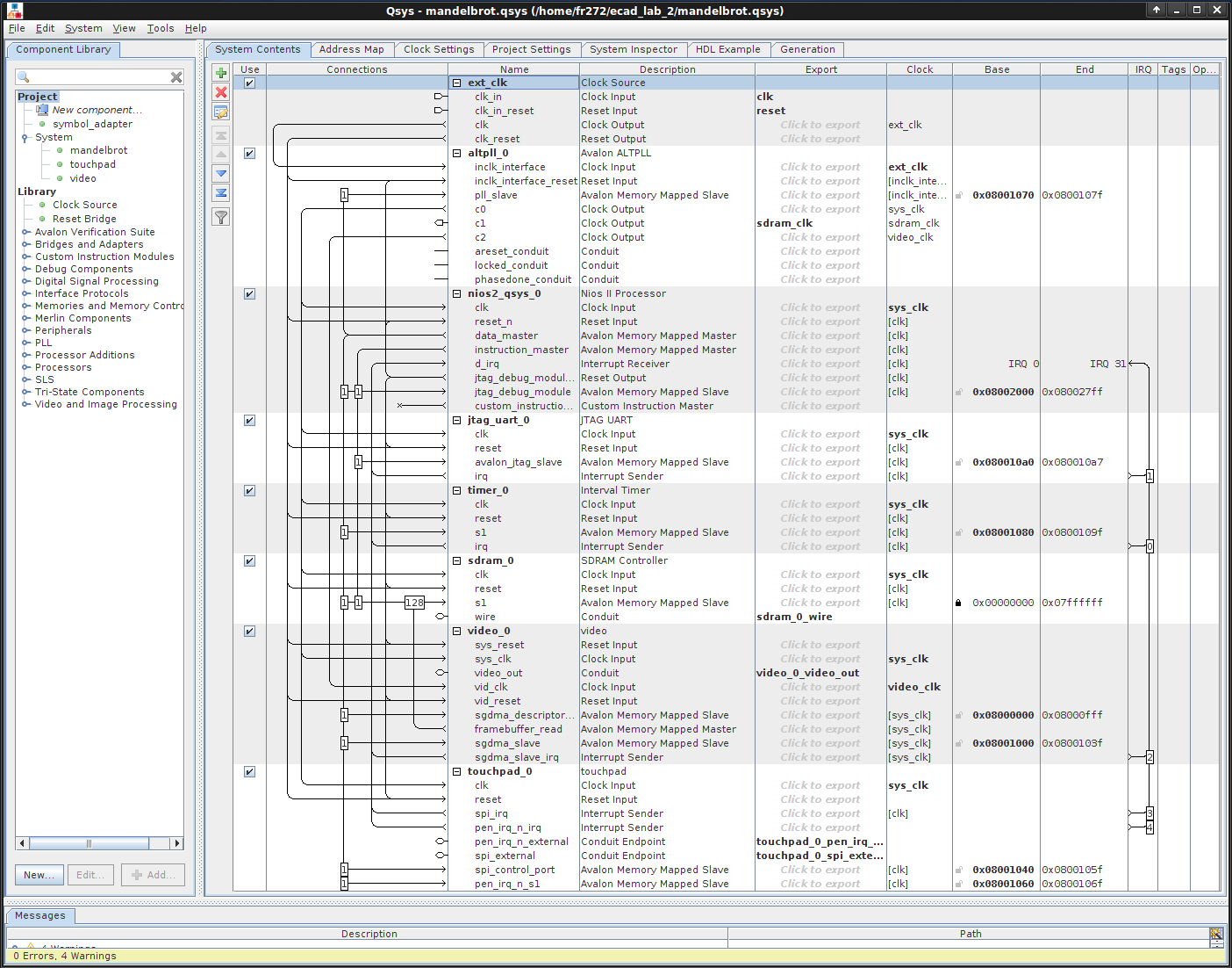
At this point if you have followed the instructions correctly your System Contents should look similar to that pictured on the right.
Generation
Click the Generation tab then click Generate. This generates all of the interconnect logic, etc. If the generation phase reports a "Your design contains errors..." warning, you will have to fix them before going any further. Look in the "Messages" pane for error messages which should give you clues as to what needs fixing. For example, typing "0x8..." rather than "0x08.." as a base address will cause problems.
Addition
Click Project | Add/Remove Files in Project..., click ... by File name:, double click the directory mandelbrot then synthesis then mandelbrot.qip (you may need to change the file type to do this) then click Add and finally OK.
Instantiation
Usually we click the HDL Example tab, copy this and then paste into the toplevel module and connect up. To help you we've provided what we did below. If you haven't renamed any components then following should work if you past it into the body of your toplevel.sv file and remove previous reset and other logic (e.g. driving the LEDs). If you do run into naming problems, compare the HDL Example in Qsys against what is below and adjust any differences.
// logic to debounce and synchronize external reset button (KEY[0])
logic [20:0] rst_dly;
logic RESET_N;
always_comb RESET_N = rst_dly[20];
always_ff @(posedge CLOCK_50)
	if(!KEY[0]) rst_dly <= 0;
	else if(!rst_dly[20]) rst_dly <= rst_dly+1;

// convert 24-bit colour to 18-bit colour for the LCD
logic [7:0] r, g, b;
always_comb begin
    HC_R <= r[7:2];
    HC_G <= g[7:2];
    HC_B <= b[7:2];
end

// output status LEDS (which TTCs are active)
logic [63:0] status;
always_comb begin
    LEDG[7:0] <= status[7:0];
    LEDR[17:0] <= status[25:8];
end

// instantiate the Qsys system
mandelbrot u0 (
    .clk_clk                              (CLOCK_50),
    .reset_reset_n                        (RESET_N),
    .sdram_clk_clk                        (DRAM_CLK),
    .touchpad_0_spi_external_SCLK         (HC_ADC_DCLK),
    .touchpad_0_spi_external_SS_n         (HC_ADC_CS_N),
    .touchpad_0_spi_external_MOSI         (HC_ADC_DIN),
    .touchpad_0_spi_external_MISO         (HC_ADC_DOUT),
    .touchpad_0_pen_irq_n_external_export (HC_ADC_PENIRQ_N),
    .video_0_video_out_RGB_OUT            ({b,g,r}),
    .video_0_video_out_DEN                (HC_DEN),
    .video_0_video_out_HD                 (),
    .video_0_video_out_VD                 (),
    .video_0_vid_clk_out_clk              (HC_NCLK),
    .sdram_0_wire_addr                    (DRAM_ADDR),
    .sdram_0_wire_ba                      (DRAM_BA),
    .sdram_0_wire_we_n                    (DRAM_WE_N),
    .sdram_0_wire_cke                     (DRAM_CKE),
    .sdram_0_wire_ras_n                   (DRAM_RAS_N),
    .sdram_0_wire_cas_n                   (DRAM_CAS_N),
    .sdram_0_wire_dqm                     (DRAM_DQM),
    .sdram_0_wire_dq                      (DRAM_DQ),
    .sdram_0_wire_cs_n                    (DRAM_CS_N),
    // export status bits from TTCs
    // commented out until you need have added TTCs
    // .status_leds_export                   (status)
);
Build/Run
You should can now compile the project and program it onto the Cyclone IV. The compilation will probably take a while, but luckily the next section can be done during the build if you like.
Starting Nios-II EDS
Open Teaching Packages | Computer Laboratory | Altera 11.0 | Nios II EDS 11.0 | Nios II 11.0 Software Build Tools for Eclipse from the PWF start menu. When asked to select a workspace, create a subdirectory of ecad_lab_2 named software and select it then click OK.
Starting a project
Click File | Nios II Application and BSP from Template. The BSP is the Board Support Package, a collection of libraries tailored to your particular Qsys project. Click ... by SOPC Information File name: and select mandelbrot.sopcinfo under ecad_lab_2. Type mandelbrot as the Project name:. Select Blank Project under Templates and click Finish.
Download the C source for a Mandelbrot plotter for the Nios-II. Click File | Import then select General | Archive File and click Next >. Click Browse... next to From archive file: and find where you downloaded the Mandelbrot plotter. Click Browse... next to Into folder: and click mandelbrot. Finally, click Finish. Now go to Project | Build All.
If you have errors of the form "'SYMBOL' undeclared (first use in function)" and you renamed some of the components in Qsys at this point you will need to make corresponding changes to several constants in init_drivers().
Otherwise, assuming you have completed programming the Mandelbrot Qsys system onto the Cyclone IV, go to Run | Run Configurations... and select Nios II Hardware. We didn't include a System ID nor a Timer in the design, so you'll need to tick the boxes to ask the system to ignore these (under the Target Connection tab). After some delay you should see a black and white plot of the Mandelbrot set as well as how long it took to generate under the Nios II Console.
Note that whenever you regenerate your Qsys project, you will need to regenerate your BSP. If you don't you will get the error make: *** [../mandelbrot_bsp/-recurs-make-lib] Error 2. Rebuild the BSP by right clicking mandelbrot_bsp under Project Explorer then clicking Nios II | Generate BSP.
Compilation options
The rest of this lab will involve pursuing one approach towards accelerating the speed at which the Mandelbrot set plot is generated. One particularly easy way of speeding up the generation at the moment would be to turn on compiler optimisations and turn off debugging symbols.
Right click mandelbrot under Project Explorer and click Properties. Select Nios II Application Properties. Turn Debug level to Off and Optimization level to Level 3. Rerun the project and note the approximately x2 speedup. Note that if you do want to use the debugging facilities later you should turn Debug level to On otherwise debugging will operate on disassembled assembly rather than the source code and Optimization level to Off otherwise a single line of C may no longer have an exact correspondence to any particular group of instructions making single stepping tricky.