|
|
|||||
| Computer Laboratory Workshop Six |
||
| Computer Laboratory > Course material 2006-07 > Hardware Practical Classes > Workshop Six |
Workshop Six - Digital-to-Analog ConversionIntroductionIn this workshop, you will build two different kinds of digital-to-analog converter (DAC). The first uses a resistor network called an R2R ladder, and works in parallel, i.e. a binary value is fed into the resistor network in parallel and a corresponding analogue signal is output. The second DAC (known as a 1-bit DAC) is all digital and uses a clock and a state machine to produce a single output. The output fed through an analogue low pass filter which removes the high frequency digital component leaving an average of the ones and zeros as the analog output. The more ones in the sequence means the output voltage rises, more zeros and the output voltage falls. Components
Step 1: R2R ladder DAC
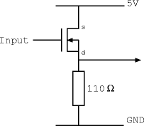
Step 2: Build the R2R DACTask 1: Construct the inverted DAC using 4.7K Ohm resistors to replace the 2 Ohm resistors, and two 4.7K Ohm resistors in parallel to replace the 1 Ohm resistors. Use the toggle switches as input and check that the output voltages are correct as the inputs are changed. Task 2: Now connect a voltage follower and resistor load as shown below. Answer questions 3, 4 and 5.
 Voltage Follower Driving a 110 Ohm Load Step 3: Build a 1-bit DAC (Bitstream DAC)
AssessmentTicking criteria: Write up your experimental data and answer the following questions. Once your work has met the Common Ticking Criteria (see Introduction), get your work ticked by an assessor. Remember that you need to hand in this assessed exercise as part of your portfolio of work (see the Head of Department's notice). Questions
1. Using Ohm's law and the formula for resistors in parallel, what is
the output voltage of the R2R DAC when inputs A and B are connected to
each combination of ground and 5 volts? Please display the results as
a table. |
