|
|
|||||
| Computer Laboratory Workshop One |
||
| Computer Laboratory > Course material 2004-05 > 1A Hardware Workshops > Workshop One |
Workshop One - Electronic DieIntroductionThe purpose of this lab is to build a simple electronic die from LEDs. Before you start, make sure you understand how the holes in you breadboard are connected (see Appendix A). Components
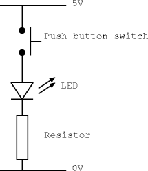
Step 1 - wiring up one LEDFirstly, you need to learn how to turn on an LED! If you connect a LED across the power supply, it will draw enough current to destroy itself. To limit the current which passes through the LED, a resistor must be connected in series with it.
 PLEASE MAKE SURE that you are using the correct value resistors, if you are not ask a demonstrator! You could destroy the LED. When the LED is lit correctly, the voltage drop across it will be approximately 1.6V and the current flowing through it should be around 15mA. To work out the correct value for the resistor, consider what the voltage across it and the current flowing through it should be and then use Ohm's law. i.e.:
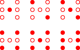
The nearest available value is 220 Ohms. Task: Construct the above circuit and check that the LED lights when the button is pressed. Step 2 - Binary to Dice DecoderFor this workshop you will need to arrange 7 LEDs in the following pattern to emulate the spots on a die. Remind yourself which LEDs you will need to turn on to make the six possible face values.  Design task: Design the combinatorial logic function to drive the LEDs. The input should be a 3-bit binary number, ranging from 1 to 6, and there should should one output for each LED. Begin by drawing a truth table with the 3-bit binary number as input and 7-bit die output. How can you simplify the truth table to remove replicated columns? From simplified truth table, use Boolean optimisation (e.g. k-maps) to produce a minimal function for each LED. Then use DeMorgan's laws to reduce these expressions so that they can be built from NAND gates. Implementation task: Arrange the seven LEDs on your breadboard to make the pattern shown above, making sure that each has the correct resistor in series with it. Use your 74HC00 ICs (each of which contain 4 NAND gates) to construct this function and connect the output to the LEDs. Test the circuit by connecting the 3 inputs to toggle switches. Step 3 - Make the die spinTask: Use a 74HC193 counter chip as a replacement for the switches. Make sure that the unused input pins are connected appropriately. Apply a 100KHz clock to the 'count up' clock input of this chip. To make the counter pausable, connect the clock through one of the blue push button switches. You should now have a usable 8-sided die! Optional Bonus StepTask: How could you use the 'load' facility of the 74HC193 along with another 74HC00 to make your die count in the sequence 1, 2, 3, 4, 5, 6? Try implementing it. AssessmentTicking criteria: Write up your design and answer the following questions. Demonstrate that your eight sided die works. Once your work has met the Common Ticking Criteria (see Introduction), get your work ticked by an assessor. Remember that you need to hand in this assessed exercise as part of your portfolio of work (see the Head of Department's notice). Questions
1. What die patterns are displayed for binary inputs 000 and 111? |
