|
|
|||||
| Computer Laboratory Breadboard |
||
| Computer Laboratory > Course material 2004-05 > 1A Hardware Workshops > Breadboard |
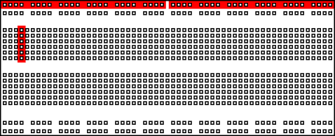
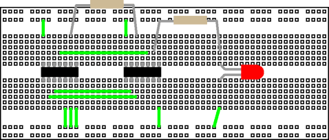
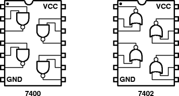
Appendix AUsing the breadboardA breadboard has many strips of metal which run underneath the board. The metal strips are laid out as shown in red below, horizontally along the two lines at the top and bottom, and vertically to join six holes together in the central section.  These strips connect the holes on the top of the board. This makes it easy to connect components together to build circuits. To use the breadboard, the legs of components are placed in the holes (the sockets). The holes are made so that they will hold the component in place. Each hole is connected to one of the metal strips running underneath the board. The long top and bottom row of holes are usually used for power supply connections. The rest of the circuit is built by placing components and connecting them together with jumper wires. Chips can be placed in the middle of the board so that half the legs are on one side of the middle line and half are on the other side. A completed circuit might look like the following.  Careful planning of the circuit layout simplifies wiring, minimizes errors and makes debugging easier. Try to arrange the circuit for a logic signal flow. This helps anyone looking at the board to find easily sections of the circuit and trace signals through it. Wherever possible, all ICs should be pointed in the same direction to reduce the chance of one being put in backwards. this also makes it easier to keep track of pin numbers when wiring and debugging. Colour coded wiring is an easy way to reduce wiring errors and aid the process. If possible, build and test one section of the circuit at a time to simplify debugging before connecting the sections together. Keep connecting wires as short as possible and route them around ICs so that a defective IC can be replaced without removing and often incorrectly replacing the wires. While all this may seem labourious, the time spent in careful construction and checking is well repaid by having more circuits work first time. The pinouts of all the ICs used in the hardware labs should be available as a booklet. Never take the pinout of an IC for granted!. Below are two similar chips: the 7400 and 7402, are quad NAND and quad NOR gates respectively. Note the different pinout.  |
