
Course pages 2015–16
ECAD and Architecture Practical Classes
Exercise 1: Human Input on DE1-SoC teaching board
Scheduling
You should aim to start this exercise during week 2 and complete it in week 2 or week 3. You will not be able to begin Exercise 2 (RISC-V processor) until the material is covered in lecture 6 of Computer Design.
Introduction
We have mated a DE1-SoC board from Terasic with our own input/output board mounted on the back. Output is in the form of an LCD and some tri-colour LEDs. For this exercise we will focus on the inputs: rotary dials and switches.
Rotary Dials
Rotary encoders are widely used for human input from old mechanical mice to the rotary knob you find on a Nest thermostat. There are also many industrial applications: see Wikipedia on rotary encoders for details.
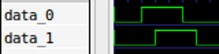
The two rotary dials on the DE1-SoC I/O board are incremental rotary encoders which have mechanical contacts. There are two outputs which produce a Gray code sequence when they are turned. A full rotation is 24 discrete steps. For a clock-wise turn, a clean signal will have a waveform as follows:
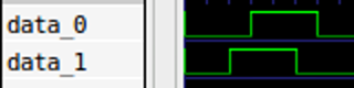
For a counter-clock-wise turn, the waveform looks as follows:
The output signal is digital and asynchronous; the time between two edges on a waveform is only determined by the physical action of turning the knob. Physically this is implemented by moving a conductive part over a two-channel "code track" on a disc. Wiggle in the conductive part causes a bouncy output signal from the rotary encoder. In practice, this means that if you measure the signal produced by a clock-wise turn, the result will look more fuzzy. By using an oscilloscope, we measure the following: `

Although we can definitely recognise the square wave of a counter-clock-wise turn in this diagram, the noise we observe could make it difficult to make decisions in a digital system. In two places, a high signal drops to low for periods as much as 0.2ms. To turn this signal into a clean square wave that we can interpret in some control logic, we must first apply some filtering known as debouncing.
Task 1 - Debouncer
Implement debouncing logic in SystemVerilog. It will take the following input signals:
- A clock signal
- A bouncy signal
The output of this component is a debounced (i.e. cleaned up) signal
Assume that this logic block receives an input clock of 50MHz. Your logic should sample the input line and change the value of it's output line only if a signal has been in the same state for a certain amount of samples. Choose this time interval such that it is long enough to detect the spikes as seen in the measurement above, but short enough to still be able to determine which of the two lines was set to high first.
We encourage you to do test driven development using the simulation techniques you have already learnt. To help you get started, we've created a simple test bench tb_debounce.sv and a suitable "do" script tb_debounce.do.
Download rotary.zip. Create a directory exercise1 and unpack it inside.
When implementing this component in SystemVerilog, please store the file as "debounce.sv" and use the following template so that it matches up with the test bench.
module debounce
  (
        input wire       clk,       // 50MHz clock input
        input wire       rst,       // reset input (positive)
        input wire       bouncy_in, // bouncy asynchronous input
        output reg       clean_out  // clean debounced output
   );

        /* Add wire and register definitions */

        /* Add synchronous debouncing logic */

endmodule
Tips:
- See the Computer Design lecture notes for a debouncer example.
- Ensure that you synchronise your asynchronous input using a two flip-flop synchronise described in the Computer Design lecture notes.
Task 2 - Rotary Decoder
Create a new SystemVerilog module that implements control logic for interpreting the output of the rotary encoder. The input of your control logic will take three signals:
- A 50MHz clock signal.
- A reset signal (active-high, meaning that reset is asserted when it's signal is 1).
- A two-bit rotation signal.
It's output will be:
- An rotary_pos 8-bits integer value representing the position of the knob relative to it's begin position.
- A rot_cw signal asserted for one cycle when a clock-wise rotation is detected.
- A rot_ccw signal asserted for one cycle when a counter-clock-wise rotation is detected.
Your logic is expected to perform the following:
- Debounce the input signals.
- For every clock-wise detected step, increment the output value by one and assert the rot_cw signal for one cycle.
- For every counter-clock-wise detected step, decrement the output value by one and assert the rot_ccw signal for one cycle.
- When the reset signal is asserted, reset the counter to 0.
When implementing this component in SystemVerilog, please store the file as "rotary.sv" and use the following template.
module rotary
  (
        input  wire clk,
        input  wire rst,
        input  wire [1:0] rotary_in,
        output logic [7:0] rotary_pos,
        output logic rot_cw,
        output logic rot_ccw
   );

        /* Add wire and register definitions */

        /* Instantiate debouncing components */

        /* Synchronous output value manipulation logic */

 endmodule
Test your module using tb_rotary.sv and tb_rotary.do supplied in the zipfile.