
ECAD and Architecture Practical Classes
Lablet 1.2 - Architecture and Software
A component is a functional unit with a well-defined interface. The most basic components, from synchronisers to simple processors, are written in an HDL, such as SystemVerilog. We now move away from writing Verilog and focus on building custom processor architectures using existing components as building blocks.
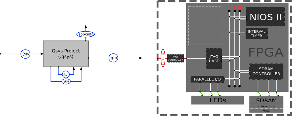
Qsys operates at the component level of abstraction, allowing hierarchical systems to be connected together using streaming (point-to-point) and bus (master-slave) paradigms. Communication with bus devices is memory-mapped: each device is represented as an address range; reading and writing data to specific addresses causes analogous activity on the corresponding device.
The aim of this section is to guide you through building the FPGA architecture as shown. It consists primarily of a NIOS II processor acting as a bus master with some memory (SDRAM) and Parallel I/O (PIO) adapters as slaves. The PIOs will provide a memory-mapped interface to a few board peripherals (e.g. the red LEDs).
The result will be a generated hierarchy of Verilog components, which you will instantiate in a Quartus project and synthesise to the tPad FPGA.
Getting Started
You first need to create a new Quartus project using the same procedure as for the first lab, calling it ecad_lablet_1_2 this time. Note: don't forget to include the pin definition file as before.
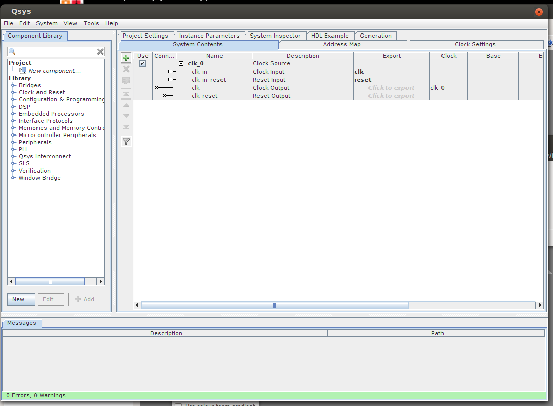
Start Qsys by going to Tools | Qsys.
On the left is a list of components, grouped by common interface. The main panel is tabbed; System Contents is where components are dropped and connected together.
Two important interfaces are standardised: Avalon-MM components interact in a memory-mapped (bidirectional, addressed) fashion; Avalon-ST components communicate by streaming (unidirectional, optionally has channels).