
ECAD and Architecture Practical Classes
Ring based request/response message router
Introduction
The final design will consist of the Nios-II sending off individual points to be calculated by a processor-farm-on-a-programmable-chip of TTCs. In FPGA design, particularly when trying to exploit parallelism by replicating a single component several times, resource usage can become a critical. Attaching a memory mapped master to many memory mapped slaves will introduce lots of multiplexing logic.
For example, for a master to read data from 4 different memory mapped slaves, each with 4 words the multiplexing for the response may look something like:
                     |\
   readdata_0[0:31] -| \
                     |  |
                     |  |----------\
                     |  |           \       |\
   readdata_1[0:31] -| /             \------| \
                     |/|                    |  |
                       |addr[3]             |  |---readdata[0:31]
                     |\                     |  |
   readdata_2[0:31] -| \             /------| /
                     |  |           /       |/|
                     |  |----------/          |addr[2]
                     |  |
   readdata_3[0:31] -| /
                     |/|
                       |addr[3]
Note the following:
- There is corresponding demultiplexing on the request side;
- Each multiplexer must be replicated 32 times, once for each bit in the word;
Rather than using a tree structure to route messages, we will use ring structure. This will ensure the per processor resource usage of the TTC in the final design is closer to its individual, isolated cost. The primary disadvantage of this routing structure is that it introduces latency (O(n) as opposed to O(lg(n))), however, this application is mostly throughput bound, at least at the generation speeds aimed for here.
Ring
We have created some SystemVerilog which instantiates up to 64 TTCs and connects their input and output ports in a ring using Avalon Streaming interfaces. These interfaces include a channel number which is used to stear data to TTCs and to identify which TTC produced data.
Download:
- ring_ttc.sv - the SystemVerilog describing the ring network
- ring_ttc_hw.tcl - a TCL file generated by Qys which contains the parameters needed to connect it to the system.
Take a look at ring_ttc.sv. It consists of three modules:
- ring_switch which instantiates one TTC and wraps it in a simple ring switch. There is one Avalon input stream and one Avalon output stream coming in and out of this module. Data coming in has its channel number inspected and if it is detined for this node it is fowarded to the TTC otherwise it is sent to the output port. Data from the TTC is sent to the output port with the corresponding channel number added. Note that the names of the inputs and output might look rather odd but they correspond to the default names that Qsys expects which makes importing the module easier.
- ring_ttc is the toplevel module. It too has single input and output Avalon Streaming interfaces. Inside you will see a generate block containing a for loop which instantiates num_ttc copies of the ring_switch, i.e. num_ttc TTCs.
- TestRing which can be used to test the system in simulation.
If you open up Qsys (or hit "Refresh" if Qsys is already open) then the new ring_ttc component should appear.
Making a new Qsys component (this can be skipped)
Since we provided you the ring_ttc_hw.tcl file, you do not need to do this step. But if you are interested in seeing how to import a component into Qsys and generate the TCL file, here goes...
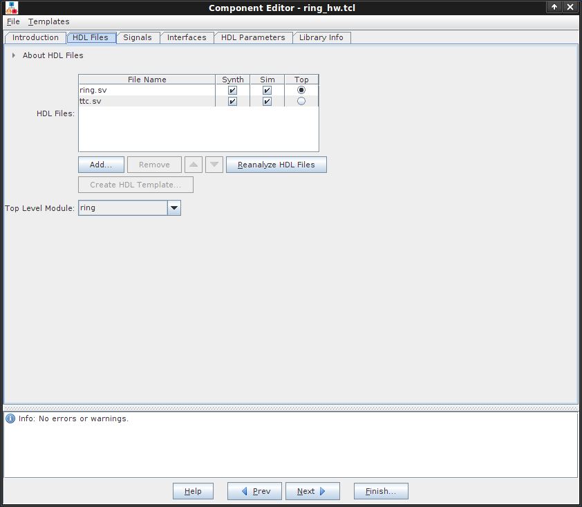
Open Qsys and click File | New component.... Click the HDL Files then click the Add... button and select ring_ttc.sv. Make sure ring_ttc.sv is selected as Top and that ring_ttc is selected as the Top Level Module:.
Under the Interfaces tab, scroll down to in (Avalon Streaming Sink) and set its Associated Reset: to reset, the number of Data bits per symbol to 32 and the Maximum channel to 255. Do the same thing for out (Avalon Streaming Source). Click Finish... and answer Yes, Save when asked (this will generate the TCL file).
When you come to add ring_ttc to your project tou'll notice at this point that if you refresh the system by pressing F5, a new error appears regarding TOP_LEVEL_MODULE. This is a bug in Qsys. To fix it, open ring_hw.tcl, delete the line set_module_property STATIC_TOP_LEVEL_MODULE_NAME "", save it and refresh your Qsys system by pressing F5.
Add memory-mapped FIFOs
We're going to use memory mapped FIFOs to talk to the ring of TTCs. You can find this component under Component Library | Memories and Memory Controllers | On-Chip | On-Chip FIFO Memory. We need to add two of these, one with a memory mapped write port and a streaming read port and the other a mirror image (i.e. a streaming write port and a memory mapped read port):
- Memory mapped writer:
- Tick singleResetMode
- Set the Depth to 128, tick Allow backpressure, select Clock setting: Dual clock mode
- Under Status port tick Create status interface for input and untick the others
- Under Input select AVALONMM_WRITE
- Under Output select AVALONST_SOURCE
- Under Avalon-ST port settings select Bits per symbol: 32, Symbols per beat: 1, Error width: 8, Channel width: 8 and untick Enable packet data
- Memory mapped reader:
- Tick singleResetMode
- Set the Depth to 64, tick Allow backpressure, select Clock setting: Dual clock mode
- Under Status port tick Create status interface for output (note: output this time, not input) and untick the others
- Under Input select AVALONST_SINK
- Under Output select AVALONMM_READ
- Under Avalon-ST port settings select Bits per symbol: 32, Symbols per beat: 1, Error width: 8, Channel width: 8 and untick Enable packet data
In the System Contents window, select the first FIFO, hit Ctrl-R and change its name to fifo_write. Set the second FIFO's name to fifo_read. Connect fifo_write,out to fifo_read,in. Connect fifo_write,clk_in and fifo_read,clk_out to the sys_clk and their other clocks to video_clk (you'll see why when we connect ring_ttc). Connect the memory mapped interfaces to the data interface on the NIOS.
Testing memory mapped FIFOs
Test the system you've built by generating the system in Qsys and then synthesising it in Quartus. You will then need to write some C code for the Nios to exercise the FIFOs using the altera_avalon_fifo_util.h library in the board support package. The following example you could add to your C code to test the ring out by writing values on channels 20,21,22. If there are no TTCs on these channels then the data will be routed around the ring without going to a TTC and will be sent back to the NIOS. Use this code as a basis of the code you will need to write to communicate with the TTCs.
#include <stdio.h>
#include <system.h>
#include <io.h>
#include "altera_avalon_fifo_util.h"

void test_fifo(void)
{
  int j;
  puts("Starting test_fifo\n");
  // initialise fifo_write
  altera_avalon_fifo_init(FIFO_WRITE_IN_CSR_BASE,
      0, // disable interrupts,
      2, // almost empty level
      FIFO_WRITE_IN_FIFO_DEPTH-2); // almost full level
  // initialise fifo_read
  altera_avalon_fifo_init(FIFO_READ_OUT_CSR_BASE,
      0, // disable interrupts,
      2, // almost empty level
      FIFO_READ_OUT_FIFO_DEPTH-2); // almost full level
  // write 10 values to channels 20, 21 and 22
  // N.B. if there are no TTCs on these channels then data from the NIOS
  // will be routed around the ring and back to the NIOS without being modified.
  for(j=0; j<10; j++) {
    if(altera_avalon_fifo_write_other_info(FIFO_WRITE_IN_BASE, FIFO_WRITE_IN_CSR_BASE, (20 + (j % 3))<<8) != ALTERA_AVALON_FIFO_OK)
      printf("Failed to write channel number when j=%d\n",j);
    if(altera_avalon_fifo_write_fifo(FIFO_WRITE_IN_BASE, FIFO_WRITE_IN_CSR_BASE, j) != ALTERA_AVALON_FIFO_OK)
      printf("FAILED to write %1d since FIFO is full\n",j);
  }
  // read back data and channel information from the FIFOs
  for(j=0; (altera_avalon_fifo_read_level(FIFO_READ_OUT_CSR_BASE)>0); j++) {
    int data = altera_avalon_fifo_read_fifo(FIFO_READ_OUT_BASE,FIFO_READ_OUT_CSR_BASE);
    int status = altera_avalon_fifo_read_other_info(FIFO_READ_OUT_BASE);
    int chan = (status>>8) & 0xff;
    printf("Read back from FIFO: %1d  chan: %1d\n",data,chan);
  }
}
Add a ring of TTCs
There is a minor bug here - Qsys doesn't like the debug code in ttc.sv and for some reason we didn't pick this up in testing. The ttc.sv has been updated to add some:
`ifdef MODEL_TECH
and
`endif
statements around the simulation code so that Qsys ignores it. We recommend you add these to your version of ttc.sv, specifically around the module DisplayTraces (definition and use).
Double click ring_ttc from the Component Library (or select and hit the Add... button). This will open up a window containing parameters for the TTC. Enter 16 for the num_ttc and the name of your fractal machine code MIF file for the progpath_mif. The progpath_rmb should be greyed out and is not needed (it is only used by the simulator). Then click Finish. Note that you should be able to add up to 64 TTCs but the more you add the more time Quartus will spend doing place & route. 16 should be sufficient to meet the ticking criteria.
Since this version of the TTC is unpipelined, it has long chains of combinational logic which have pushed its Fmax almost down to 40Mhz, therefore it will be clocked according to video_clk. Connect the output stream from fifo_write to the input of the ring_ttc. Connect the output of the ring_ttc to input stream of fifo_read. Qsys will then complain that the timing on the streams doesn't match since the ring_ttc has a zero read latency and the FIFOs have a one cycle read latency. This is easily fixed using menu option System | Insert Avalon-ST Adapters.
Generate the system in Qsys and synthesize in Quartus (this will take quite a bit of time). Since you've already tested one TTC running your fractal code in simulation, and we're already tested the ring_ttc, there is a reasonable chance that you'll only need to build the hardware once. Whilst you're waiting for the hardware to build, get on with the software!
Modifying the Nios-II program
The next and final task is to modify mandelbrot.c to make use of the 16 TTCs running Mandelbrot accelerators. Make use of the test_fifo code (above) as a template to initialise the FIFOs and then write and read data to/from the TTCs.
Benchmark it
Once you've successfully run your program, you should notice an approximately x10 speedup over the Nios-II only implementation running at -O3. The ticking criteria is to get the Nios-II + TTCs to render a full screen mandelbrot with a maximum of 255 iterations per pixel in under 10 seconds. We'll have a competition to see if people can do much better than this.