
ECAD and Architecture Practical Classes
Renderer
The first stage of this project is to add code to the renderer module to draw on screen the current grid status and the cursor.
The current state
The grid is stored in a section of Dual-Ported RAM, with one byte per cell. A zero-byte indicates a dead cell, whilst a non-zero byte indicates a live one. The grid consists of 40 cells horizontally, and 32 cells vertically. The cells are numbered left-to-right, top-to-bottom starting at 0. I.e. the byte address for the cell at position (x,y) is given by ((40 * y) + x). The addr output of the renderer is the address given to the frame buffer, and the data input is the output from the frame buffer. The frame buffer registers the address inputs, but does not register the data outputs from its memory.
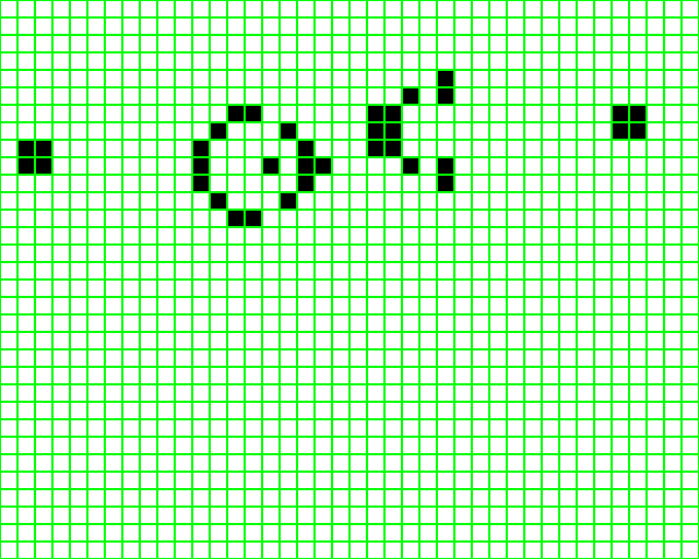
Each cell should be 32*32 pixels in size, and have a border of 1 pixel to enable you to view individual cells when there is a large expanse of cells in the same state. A live cell should be one colour (e.g. black) and a dead cell another colour (e.g. white). Once this code has been written, compiled and run the project, you should end up with a screen showing the pattern below (the dual-port RAM is preloaded with the pattern):
The cursor
The cursor position is given as an output of the mouse_logic module, and so will need to be connected to the renderer appropriately. Code will then need to be added to draw a cursor on screen at the current position. This can be done in a similar fashion to drawing the round ball in the optional section at the end of the previous lab. Note, however, that the cursor has not got the same height and width, the parameters that need to be used are `cursorwidth and `cursorheight, these can be found in defines.v as before. The following code may be useful. Be careful to ensure the cursor is drawn on top of all other graphics on the screen, and make sure the cursor has a black outline, just like the normal pointer.
  module cursor_shape(
      input [3:0] x,
      input [4:0] y,
      output pixel
      );

      assign pixel = linepattern[x];

      reg [0:11] linepattern;

      always @(*)
          case(y)
              5'h00: linepattern <= 12'b100000000000;
              5'h01: linepattern <= 12'b110000000000;
              5'h02: linepattern <= 12'b111000000000;
              5'h03: linepattern <= 12'b111100000000;
	      5'h04: linepattern <= 12'b111110000000;
	      5'h05: linepattern <= 12'b111111000000;
	      5'h06: linepattern <= 12'b111111100000;
	      5'h07: linepattern <= 12'b111111110000;
	      5'h08: linepattern <= 12'b111111111000;
	      5'h09: linepattern <= 12'b111111111100;
	      5'h0a: linepattern <= 12'b111111111110;
	      5'h0b: linepattern <= 12'b111111111111;
	      5'h0c: linepattern <= 12'b111111110000;
	      5'h0d: linepattern <= 12'b111111110000;
	      5'h0e: linepattern <= 12'b111001111000;
	      5'h0f: linepattern <= 12'b110001111000;
	      5'h10: linepattern <= 12'b100000111100;
	      5'h11: linepattern <= 12'b000000111100;
	      5'h12: linepattern <= 12'b000000011110;
	      5'h13: linepattern <= 12'b000000011110;
	      5'h14: linepattern <= 12'b000000001100;

	      default: linepattern <= 12'b000000000000;
        endcase
  endmodule

  module cursor_outline(
      input [3:0] x,
      input [4:0] y,
      output pixel
      );

      assign pixel = linepattern[x];

      reg [0:11] linepattern;

      always @(*)
          case(y)
              5'h00: linepattern <= 12'b100000000000;
              5'h01: linepattern <= 12'b110000000000;
              5'h02: linepattern <= 12'b101000000000;
              5'h03: linepattern <= 12'b100100000000;
              5'h04: linepattern <= 12'b100010000000;
              5'h05: linepattern <= 12'b100001000000;
              5'h06: linepattern <= 12'b100000100000;
              5'h07: linepattern <= 12'b100000010000;
              5'h08: linepattern <= 12'b100000001000;
              5'h09: linepattern <= 12'b100000000100;
              5'h0a: linepattern <= 12'b100000000010;
              5'h0b: linepattern <= 12'b100000011111;
              5'h0c: linepattern <= 12'b100010010000;
              5'h0d: linepattern <= 12'b100110010000;
              5'h0e: linepattern <= 12'b101001001000;
              5'h0f: linepattern <= 12'b110001001000;
              5'h10: linepattern <= 12'b100000100100;
              5'h11: linepattern <= 12'b000000100100;
              5'h12: linepattern <= 12'b000000010010;
              5'h13: linepattern <= 12'b000000010010;
              5'h14: linepattern <= 12'b000000001100;

              default: linepattern <= 12'b000000000000;
        endcase
  endmodule
Optional Exercise
As an optional exercise, modify the renderer further to display 2 icons representing dead and alive cells. This can be done simply by using a small piece of ROM on the chip, loaded with the icon data. Open up the MegaWizard Plug-In Manager as before, and this time you need the component marked RAM: 1-PORT located under Memory Compiler. Ensure Cyclone II device family is selected and give the file a name, then click next. Give the ROM a q output width of 32 bits, and 2048 words of memory (32*32 icons, with 2 icons needed). Do not register the 'q' output port. Finally, on page 5, indicate for it to use the file "icons.mif" as the memory initialisation file for this memory. Finish the wizard, and instantiate the module as usual.
Next, download the icons.mif file into the project directory. This contains data for 2 icons, stored one word per pixel, read left-to-right, top-to-bottom. The "live" icon starts at address 0x0000, the "dead" one at address 0x0400. Each pixel is stored in the format 00RR_RRRR_RRRR_GGGG_GGGG_GGBB_BBBB_BBBB to match the 10-bit wide VGA signals available. Finally, link this memory module into the renderer, and alter the code to draw the icons rather than filled rectangles. Feel free to replace the icons with ones of your own.
If you wish to create your own icons, you may find the MIF Creator program useful. This takes an image that must be 32 pixels wide and 64 high, with the icon for the "live" cell on top, and outputs a .mif file in the format mentioned above.