Hardware Setup


Next: Basic Arm Test
Up: A Test Suite for
Previous: Basic Configuration
You should have the items in Table 2 for the test:
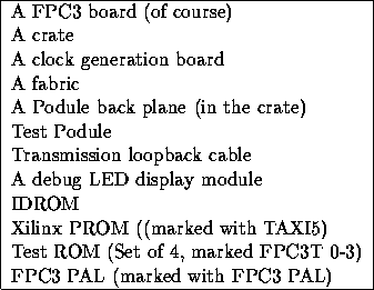
Table 2: Hardware Components
Furthermore, you need some sort of console output device. A character-based
terminal set to 4800 baud will do the job. With these components, this is the
setup we need for the test:
-
The transmission Xilinx PROM, IDROM, FPC3 PAL and test ROM are inserted
in their corresponding sockets on the FPC3 board.
-
The debug LED module is also inserted on the FPC3 board
-
Loopback cable on the transmission interface (blue end below and red
end above)
-
The test Podule is plugged into one of Podule backplane slot (any one
will do as the software will find the card), and then the backplane
plug into the FPC3 Podule backplane connector
-
Serial line connected
-
Setup crate with clock generation board and fabric board. Make
sure that the FPC3 is in IFAB 5 position.
Shaw Chuang