|
|
|||||
| Computer Laboratory PALs and the PAL Compiler |
||
| Computer Laboratory > Course material 2005-06 > 1A Hardware Workshops > PALs and the PAL Compiler |
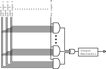
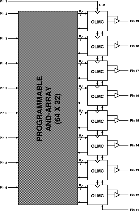
Appendix BPALs and the PAL CompilerPALsA PAL (programmable array logic) is a circuit which can be configured by the user to perform a logic function. It consists of an AND array followed by an OR array, the former being programmable. Inputs are fed into the AND array, which performs the desired AND functions and generates product terms. The various product terms are then fed into the OR array. In the OR array, the outputs of the various product terms are combined to produce the desired outputs.You will be using a small, relatively modern PAL called a GAL16V8. It has up to 16 inputs and 8 outputs. Each output is driven by a single 8-input OR gate, which in turn is driven by eight 32-input AND gates. These 32 inputs can be programmed to be connected to the 16 possible inputs to the chip and their inverses.  The output from the each OR gate is connect to an output pin through an output macrocell. This can be programmed to latch the output or feed the output signal back into AND array. For a more detailed description of this PAL, read the datasheet. PAL CompilerTo program the PAL with the functions necessary to implement a state machine, you will need a PAL compiler. This will produce a JEDEC file which is needed by the programmer. You will be using a web-based compiler. You need to type in equations using variables p2 to p9 on the input side (representing the input pins) and p12 to p19 on the output side (representing output pins).  When using the PAL Compiler you should have the above diagram in mind. The compiler expects 8 equations, one to drive each output logic macrocell (OLMC). The OLMCs in turn drive pins 19 to 12. what the 16 inputs are depends on the configuration mode of the PAL. Pins 2 to 9 are always inputs, but in registered mode pins 12 to 19 make the other 8, in complex mode pins 1, 11 and 13 to 18 are used and in simple mode pins 1, 11 to 14 and 17 to 19. The mode can be selected using the check boxes. The equations for each output (called P19 to P12, in that order) can consist of inputs, operators and brackets. The input must be refered to by the "P" followed by a number. Operators are &, |, ^ and ! for AND, OR, XOR and NOT respectively Examples:
When you have typed in your equations, click the compile button. |
