|
|
|||||
| Computer Laboratory Resistor Colour Code |
||
| Computer Laboratory > Course material 2004-05 > 1A Hardware Workshops > Resistor Colour Code |
Appendix CResistor Colour CodeResistors are normally coded with coloured bands to enable quick identification of their value. The colour code specifies the value of the resistor, in ohms, and the maximum deviation from the stated value (the tolerance). Most resistors have a manufacturer's tolerance with is adequate for most electronic applications Interpreting the Colour CodeThe four colour code bands are at one end of the component. Counting from the end, the first three (or sometimes four) bands give the resistance value and the last the tolerance. The significance of the colours is shown in the table below:
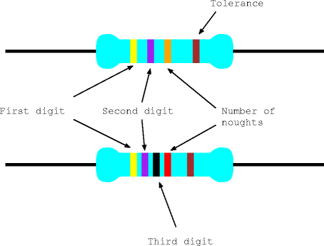
Reading the value (three band)The first two bands are used to specify the first two digits of the resistor's value. The third gives the number of noughts to be added. Thus in this example, yellow and violet give the first two digits as 4 and 7 and the number of zeros is 3 (orange) giving a value of 47000 ohms.  Four Band ResistorsMore modern resistors use four bands to specify the resistance, the first three giving the three most significant digits and the fourth the number of zeros. Yellow, violet, black, red decodes as 4, 7, 0, 00 ie. 47000 ohms. | ||||||||||||||||||||||||||||||||||||||||||||