|
|
|||||
| Computer Laboratory Workshop Three |
||
| Computer Laboratory > Course material 2004-05 > 1A Hardware Workshops > Workshop Three |
Workshop Three - Debouncing a switchIntroductionWhen using a switch as an input to a digital circuit, several pit-falls may be encountered. The problem of switch `bounce' is the subject of this experiment, what it is, and one method (an all digital method) of overcoming it. Components
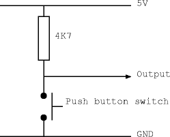
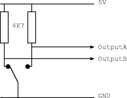
Step 1 - Watch a switch bouncingTask: Build the following circuit on a breadboard using the blue non-debounced push-switch. Connect a scope probe to the output. Look at the output on the scope as the contact is made and broken. This is best done by triggering off the switch and varying the timebase until the appropriate detail can be seen.  Step 2 - Count bouncesTask: Connect the output of the circuit in Step 1 to the clock input of the counter (make sure you connect the unused inputs appropriately). Connect the output to the 7-segment display. What should happen? Why doesn't it work? The object of the next step is to debounce the switch so that counter increments just once as the switch contact is made. Step 3 - Debouncing a double-throw switchYou may be surprised to find that a double-throw switch is easier to debounce than single throw switch, so we'll start with a double throw switch first. The circuit below illustrates a simple circuit with a double throw switch and two pull-up resistors. The switch you will be using is a break before make switch, i.e. it is mechanically incapable of connecting both switch terminals together. What is the relationship between the two outputs if bounces only appear on one contact at a time?  Task: Build the above circuit. Design and build a circuit which takes OutputA and OutputB as input and produces a debounced output. Hint: this only requires one latch. Step 4 - Debouncing the push button switchDebouncing a switch can be done in many ways, both using analog and digital techniques. For this workshop, use a PAL to implement a shift register with the switch as its input. You should not use the output of the first flip-flop since it may go metastable if the input changes too near the clock. When all of the other flip-flops in the shift register become high, the output of your debouncer should go high. When they're all low, the output should go low. Task: Design, build and test this digital switch debouncer. Optional Bonus StepHow could you use an RC (resistor + capacitor) filter to remove bounce and what will this do to the slew rate of the signal? AssessmentTicking criteria: Write up your experimental data and final design, then answer the following questions. Demonstrate that your debouncer works. Once your work has met the Common Ticking Criteria (see Introduction), get your work ticked by an assessor. Remember that you need to hand in this assessed exercise as part of your portfolio of work (see the Head of Department's notice). Questions
1. Why is a switch debouncer necessary? |
