Workshop Six - Digital-to-Analog Conversion (REVISED)
Introduction
In this workshop, you will build two different kinds of
digital-to-analog converter (DAC). The first uses a resistor network
called an R2R ladder, and works in parallel, i.e. a binary value is
fed into the resistor network in parallel and a corresponding analogue
signal is output. The second DAC (known as a 1-bit DAC) is all
digital and uses a clock and a state machine to produce a single
output. The output fed through an analogue low pass filter which
removes the high frequency digital component leaving an average of the
ones and zeros as the analog output. The more ones in the sequence
means the output voltage rises, more zeros and the output voltage
falls.
Components
- 1a prototyping board
- 1 x 110 Ohm resistor
- 6 x 4K7 resistors
- 1 x 74HC283 adder
- 1 x 74HC374 octal D-type flip-flop
- 1 x 0.1uF capacitor
- 1 x light bulb and holder
Step 1: R2R ladder DAC
|
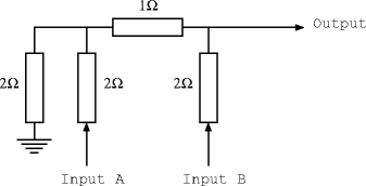
Task 1: Consider the following resistor network and answer
questions 1 and 2.
|
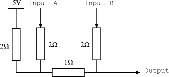
Task 2: Now consider the inverted version of this resistor
network and answer question 1 again.
|
 |
 |
Step 2: Build the R2R DAC
Task 1: Construct the inverted DAC using 4.7K Ohm resistors to
replace the 2 Ohm resistors, and two 4.7K Ohm resistors in parallel to
replace the 1 Ohm resistors. Use the toggle switches as input and
check that the output voltages are correct as the inputs are changed.
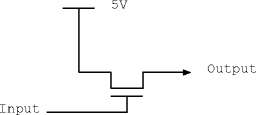
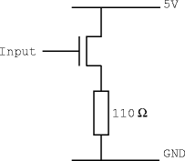
Task 2: Now connect a voltage follower and resistor load as
shown below. Answer questions 3, 4 and 5.
 |
 |
| Voltage Follower |
Voltage Follower
Driving a 110 Ohm Load |
Step 3: Build a 1-bit DAC
|
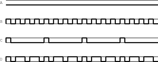
Task 1: Consider the waveforms and answer question
6.
|
 |
|
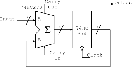
Task 2: Consider the circuit diagram below. The 74HC283 is
a 4-bit adder with carry-in and carry-out. The 74HC374 contains 8
D-type flip-flops (although this circuit only uses 4). Answer
question 7. Construct this circuit and verify that it
works. |
 |
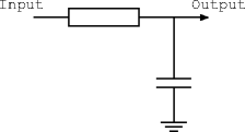
| Task 3: One way to
convert this waveform into a steady voltage (the average voltage) is
to filter the output through a low-pass filter. This will remove the
high frequency component in the waveform. Set the clock to 100KHz,
and try a resistor value of 4.7K ohm and a 0.1uF capacitor. Using an
oscilloscope, verify that the output is filtered and corresponds to
the binary input selected. Answer question 8. |
 |
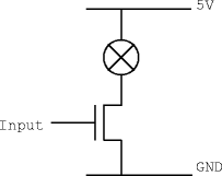
| Task 4:
Replace the output filter with a light bulb and driver transistor as
shown below. Since the temperature of the light bulb filament has
inertia, it provides a filtering effect on the light output. Answer
question 9. |
 |
Assessment
Ticking criteria: Write up your experimental data and answer
the following questions.
Once your work has met the Common
Ticking Criteria (see Introduction), get your work ticked by an
assessor. Remember that you need to hand in this assessed exercise as
part of your portfolio of work (see the
Head
of Department's notice).
Questions
1. Using Ohm's law and the formula for resistors in parallel, what is
the output voltage of the R2R DAC when inputs A and B are connected to
each combination of ground and 5 volts? Please display the results as
a table.
2. How much current will flow through this resistor network when input
B is connected to 5 volts and A to ground?
3. How much current flows through the load when it is fully turned
on? What limits the current?
4. Why is a voltage follower needed on the output of the R2R DAC
resistor network?
5. Why is the inverted version of the R2R DAC used with the voltage
follower rather than using the non-inverted form?
6. What is the long-term average voltage of each of the 1-bit DAC
waveforms?
7. For the 1-bit DAC, if the input has a fixed value 7 (0111 in
binary), and the flip-flops all start at zero, what values do the
flip-flops attain in the next 16 clock cycles and what value does
carry-out take in each cycle?
8. If you were going to design a 16-bit DAC for audio purposes
(e.g. CD player output), how would the resistor tolerances affect the
errors in the output for R2R and 1-bit DAC implementations?
9. How does the power efficiency of the R2R DAC with voltage follower
compare with the 1-bit DAC with driver transistor?
|
