
ECAD and Architecture Practical Classes
Lablet 1.1 - Synthesis
Synthesis is the process of expressing Hardware Description Language (HDL) code, such SystemVerilog, in terms of the basic units provided by the FPGA e.g. LUTs, wiring, etc. Using Quartus for this purpose, this part of the lab guides you through project creation, compilation and testing on the device.
Quartus Project Creation
First, create a new directory for this project in your filespace, perhaps called ecad_lablet_1_1.
Important: Some tools in Quartus do not like paths with spaces in, so ensure all file and directory names you choose do not have spaces in them.
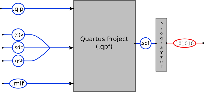
Into this folder, download the files:
- toplevel.sv
- SystemVerilog file. Each Quartus project describes a hardware component - a hierarchy of module instances with a specified root module. The interface provided by the component is the interface provided by this module.
- toplevel.sdc
- A design constraints file. Describes the hardware clocks used by the component.
- tPad_pin_assignments.qsf
- Assignments file. To interact with the hardware, this file matches (groups of) pins (e.g. those for the red LEDs) on the device to 'friendly' names (e.g. so the red LEDs can be named LEDR[17:0]). These can then be referenced in the interface of the root module.
Open Quartus
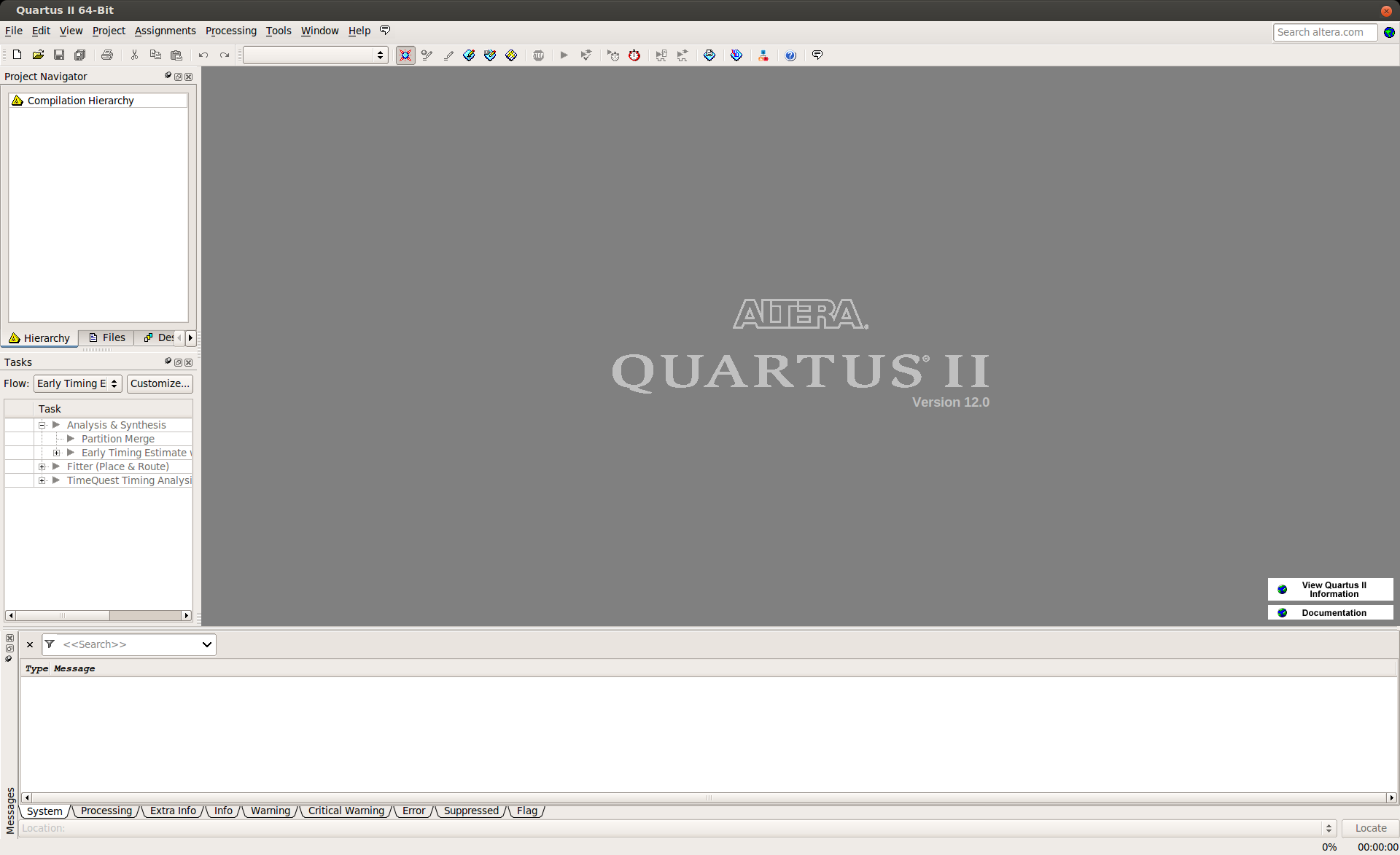
Having booted to PWF Linux, open a terminal. Type quartus & and press enter to start Quartus II 12.0 as a background child process. If you experience any licensing issues here, ask a demonstrator for help.
Once loaded, the window should ressemble the screenshot to the right. At the bottom there is the Status pane, which displays compilation messages and warnings; this may be useful when trying to debug your project. On the left is the Project Navigator, the first tab showing the logical hierarchy of the project. Below this, the Tasks pane shows the state of compilation.
Project Setup
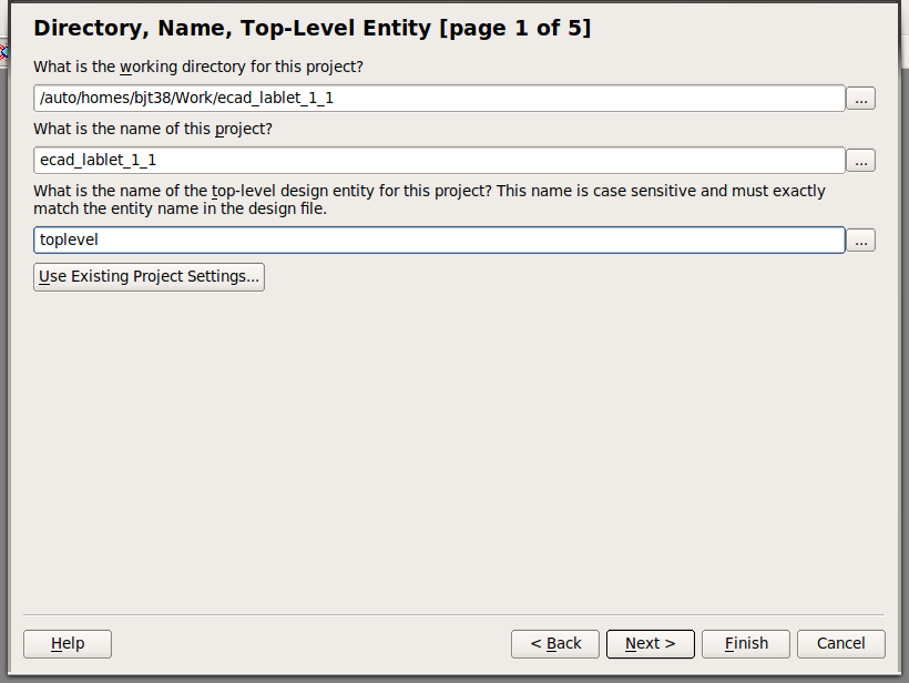
Now, select File | New Project Wizard and click Next to take you to the screen shown on the right. In the top box, enter the directory where you saved the 3 files above. In the second box, enter the name of the project; this can be whatever you like. In the lower box, type "toplevel" since this is the name of the root SystemVerilog module for this project. Now click Next.
On the next page, click Add All to add the Verilog and SDC files you downloaded earlier into the project. If these files do not appear in the list, ensure you have saved them in the same directory that you specified as the working directory in the previous step. Now click Next.
This page lets you select the device you will be programming. In the drop down boxes at the top, select the family Cyclone IV E, the package type FBGA, the pin count 780 and the speed grade 7 and ensure that Specific device selected in 'Available devices' list is checked. Next, in the Available devices list at the bottom, select the chip with the name EP4CE115F29C7. This is the serial number of FPGA that is on the tPad board.
Now click Finish to complete project setup.
Import Assignments
You need to import the pin assignments from the .qsf file you downloaded earlier. To do this, click Assignments | Import Assignments... click on the button labelled "..." and select the tPad_pin_assignments.qsf file. Click OK and then click OK again to import the assignments.
Important: Failure to assign pins will result in your design not being connected to the outside world. It will be optimised to nothing since it doesn't have any used input and output signals. You must import the assignments in every project you create.
Select HDL
Quartus uses Verilog 2001 as the default language but we'll be using SystemVerilog throughout. Go Assignments | Settings... | Analysis & Synthesis Settings | Verilog HDL Input and then select SystemVerilog-2005. Then hit Apply and OK.
Save these changes by clicking File | Save Project.