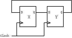
Circuit to swap two registers.
With RTL the designer is well aware what will happen on the clock edge and of the parallel nature of all the assignments and is relatively well aware of the circuit she has generated. For instance it is quite clear that this code
    always @(posedge clk) begin
        x <= y;
        y <= x;
        end
will produce the circuit of Figure~\ref{fig:swapregs}. (If x and
y were busses, the circuit would be repeated for each
wire of the bus.) The semantics of the above code are that
the right-hand sides are all evaluated and then assigned to
the left-hand sides. The order of the statements is unimportant.
However, the same circuit may be generated using a specification
where assigment is made using the = operator.
If we assume there is no other reference to the intermediate register t
elsewhere, and so a flip-flop named t is not required
in the output logic. On the other hand, if t is used, then its
input will be the same as the flip-flop for y, so an optimisation
step will use the output of y instead of having a flip-flop for t.
    always @(posedge clk) begin
        t = x;
        x = y;
        y = t;
        end
With this style of specification the order of
the statements is significant. It should not really be called RTL, but
often is in the trade.
Typically the above style of assignment statements are incorporated in
a whole set of nested if-then-else and case statements.
This allows hardware designs to be expressed using the conventional
imperative programming style that is familiar to software programmers.
The intention of this style is to give an easy to write and understand
description of the desired function, but this can result in logic
output from the synthesiser which is mostly incomprehensible.
Ideally, the user would never have to look at the output from the
synthesiser, but in practice detailed timing and testing anaysis often
requires manual inspection and intervention at the backend.
Despite the apparent power available using this form of expression,
there are severe limitations in many tools. This is because they
elaborate it down to the simple RTL parallel form. Limitations are,
for instance, each variable must be written by only one thread and
that a thread is unable to leave the current file or module to execute
subroutines/methods in other parts of the design.
The term '<em> behavioural model</em>' was originally used to denote a short program
written to substitute for a complex subsection of a structural hardware design.
The program would produce the same behaviour, but execute much more quickly
because the values of all the internal nets were not modelled. Verilog and VHDL
enabled limited forms of behavioural models to serve as the source code for
the subsection, with synthesis used to form the netlist. Therefore the behavioural
model also became the design. Today, the word 'behavioural', when applied
to a style of HDL coding, tends to simply mean that a sequential thread is used
to express the sequential execution of the statements.