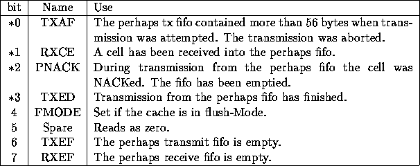
Table 9: Cache controller status lines
The cache controller is built from a xilinx 3064, supported by a xilinx 3020 and some fast PALs. It detects cache misses and controls sending and receiving the cells. This device also controls the perhaps interface, in the case of contention for transmission to the fabric the cache section always wins.
The cache controller contains a status register, which can be read by the processor. The bottom four bits of the status register may be used to signal a FIQ to the processor. An interrupt mask register is provided, a FIQ will be requested by any of the status bits with the mask set. The status bits are shown in table 9. Bits marked with an asterisk are latched when the condition happens. Those related to the transmit system may be cleared by a read of the status register with address bit 2 set. The cell received flag is cleared the fifo going empty.

Table 9: Cache controller status lines
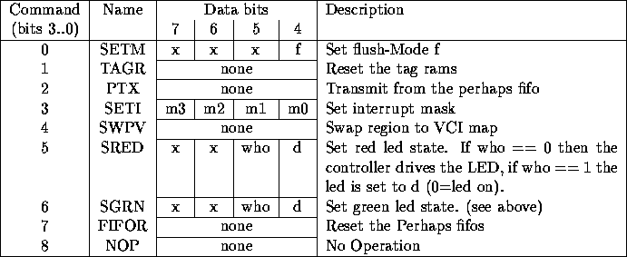
The cache controller accepts commands from the processor. The low four bits of the data indicate the operation, the top four bits are optionally some data.

Table 10: Cache controller commands
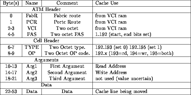
The cache controller will send a cell to request a cache line when a miss occurs. This cell may also flush an existing dirty line. It expects a cell to be returned containing the data, and the CPU is stalled until such a cell is received. The cell format used is shown in table 11.

Table 11: Cache line cell format
The cache controller gets the VCI from the dual port memory, generates the FAS, TYPE and OP codes itself, requests the address xilinx to output the Args, and moves the data itself. Arriving cells have their VCI compared to the region and Arg1 compared with the requested address and will be ignored until the correct values are presented. A cell arriving with a port controller route byte of 0x5 are stream cells and will always be accepted and put into the cache. Thus when a connection is set up for a stream the VCI for data arriving at the MDH-9 must have been set to have the low 3 bits equal to the region for the stream (the ``CacheStream'' QoS in Wanda achieves this). No checking is done on stream cell addresses.
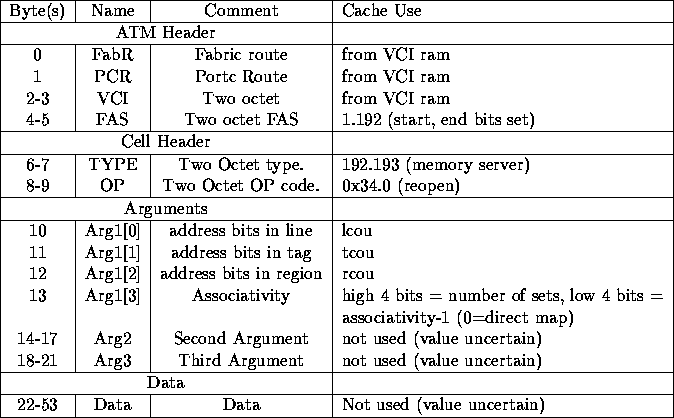
The software memory server accepts a ``reopen'' cell which may be sent
to restart (and reinitialise the memory) a connection on an existing
VCI and should also be sent as the first cell on a new connection. It
contains details of the cache organisation as shown in figure
12. The server expects an address to consist of (lsb to msb)
5 bits of offset,  bits of line,
  bits of tag and
  bits of
region. If
  then 3 is used. The server expects requests to
conform to this address range with the given associativity and may
refuse to serve any requests which suggest the cache does not match
them. Code to determine the parameters is shown in the appendix.

Table 12: Reopen memory cell format