Inkscape for 2D CAD
Inkscape is a multiplatform drawing tool (see the Inkscape web site for downloads). The Inkscape moto is "Draw Freely" which is the last thing I want to do for technical drawings (e.g. circuits or designs I wish to laser cut). What I want to do is to draw precisely, or draw constrained. Below are a few notes on how to configure Inkscape so that it is better as a "Draw constrained" tool for 2D CAD.
Units and grids
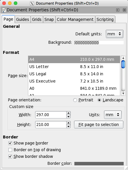
The first thing I like to do is switch to using millimeters (mm) rather than pixels (px) as the drawing unit. You can find these options under File->Drawing Properties (or shortcut Shift+Ctrl+D). The first tab in the Document Properties box allows the default units to be changed to mm, the paper to landscape A4, etc. - see below.
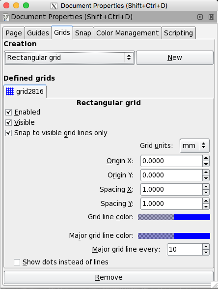
The Grids tab alows a grid to be setup. Click "New" to get a new grid. I then set the grid units to be mm, X and Y spacing to be 1mm and a major grid line ever 10 (i.e. every cm) - see below.
Dismiss the document properties box and look at the blank document. Zoom in using the + key until you can see the grid with fine 1mm grid lines and slightly bolder 1cm grid lines. The rulers at the top and left should be in mm.
Drawing precise lines and bezier curves
Select the bezier and straight line tool
 from the left tool bar. This will bring up a tool bar along the top
with snap options vis:
from the left tool bar. This will bring up a tool bar along the top
with snap options vis:

In the above figure I have enabled the following snap options (from left to right): enable snapping, snap nodes or handles, snap to cusp points, snap to grids, snap to guides.
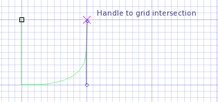
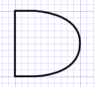
To draw a line, position the pointer at the start point of the line and left click (do not hold), click the second point, etc. If you wish to join the last point with the first, then double click. To draw a bezier curve, click and hold then drag the bezier control points. For example, in the figure below I have started to draw an AND gate starting top left, a verticle line, a small line right and then a line diagonally which I turned into a bezier with handles reaching the top and bottom of the AND gate.
The final basic AND gate is depicted below.
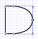
If we click on the "Edit paths by nodes" tool
 and select the AND gate you can see the nodes that the gate is
constructed from - see below.
and select the AND gate you can see the nodes that the gate is
constructed from - see below.
Width and Height
Note that the total width and height of your object includes the thickness of the line. Personally I'd prefer to see the width and height of the nodes (i.e. not including the line width), but I've not found a way to achieve this.
Scaling
If you select an object with the "Select and transform objects" tool
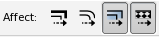
 then you can scale an object. When I'm scaling lines I prefer the line width to stay the same. This can be achived by selecting the appropriate scaling "Affect":