![]()
The Border Gateway Multicast Protocol (BGMP) is an attempt to design a true inter-domain multicast routing protocol; one that can scale to operate in the global Internet. DVMRP and DM-PIM will not do this because their flood-and-prune nature requires off-tree routers to keep per-source state. MOSPF will not do this because OSPF does not scale well enough, and MOSPF (which also distributes receivership information) scales worse. CBT and SM-PIM will not do this because the scalability of the mechanisms they use to perform group-to-RP mapping limits them.
BGMP was based on ideas from the intra-domain protocols above, but has a slightly different goal - it does not build trees of routers, but rather it builds bidirectional shared-trees of domains. Within a domain, any of the intra-domain multicast routing protocols can be used, and BGMP then provides multicast routing between the domains.
BGMP builds trees of domains that are similar to CBT trees of routers - they are bidirectional shared-trees built by sending explicit join messages towards a root domain. However BGMP can also build source-specific branches, which are similar in concept to source-specific trees in SM-PIM, but do not always reach as far as the source. The principle problem that prevents CBT and SM-PIM from scaling is that of mapping a multicast address to the unicast address of a Rendezvous Point or Core. BGMP solves this problem through a close tie-in with a hierarchical multicast address allocation scheme called Multicast Address-Set Claim (MASC). We will describe MASC in more detail in chapter ???. MASC allocates ranges of multicast addresses to domains. These address-ranges are distributed to Border-Routers world-wide as group-routes using BGP routing (which is used for unicast inter-domain routing). Such a group-route indicates the path to the root-domain for that range of multicast addresses. To make this scale, MASC allocates the address ranges dynamically in a manner that is aggregatable, so the number of group routes that need to be stored at each border-router is relatively small.
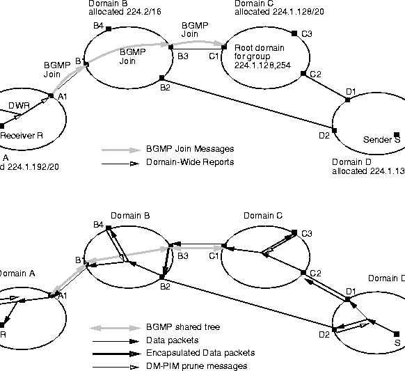
Figure 3.3 illustrates how BGMP builds a distribution tree given than group-routes have already been distributed. In this case all the domains are running DM-PIM because this simplifies the example, but in reality they would likely be running a mixture of different protocols.
Receiver R joins the multicast group 224.1.128.254. Its local router sends a Domain-Wide Report (DWR) to all the border routers in domain A. Router A1 discovers that the best route to the root for 224.1.128.254 is 224.1/16 received from its external peer router B1, so it sends a BGMP Join message to B1. Router B1 in turn looks up 224.1.128.254 and discovers its best route is 224.1.128/20 that it received from its internal peer router B3, so it sends a BGMP join message to B3. B3 repeats the process and sends a BGMP join to C1. Router C1 is a border router for the domain which has been allocated 224.1.128.254 (along with other groups), so the join message has now reached the root domain and need travel no further.
Now source S in domain D starts sending to 224.1.128.254. Its data floods through domain D and reaches all the border routers. D2 is not on the best path to the root domain, so it sends a DM-PIM prune message back towards S, but router D1 is on the best path to the root domain. It has no state for group 224.1.128.254, but forwards the data anyway to C2. C2 forwards the data into the DM-PIM domain C, and it floods through the domain. Router C3 has no state for the group, and sends a prune in response, but router C1 is on the shared tree for the group, and so forwards the data to B3. B3 wishes to forward the data into B, but it is not on the best path back to S. If it merely multicast the data into B, routers within B would drop the data as DM-PIM requires the distribution tree to be source-based. Instead, it encapsulates the data and sends it to the correct entry router (as determined by its unicast routing table), in this case B2. B2 then decapsulates the data and multicasts it into domain B, where it floods through the domain. B1 in turn forwards the data along the shared tree to domain A and hence to R.
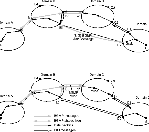
At this stage, as shown in figure 3.4A, data is flowing from S to R along the shared tree. It has flooded through the domains along the path, but has been pruned back within the domains to just the minimal tree required to deliver the data. However, B3 is having to encapsulate the data to B2, which is undesirable as routers typically are not very good at encapsulation, and also as there is a better path that the data could have taken. As B2 is not on the shared tree, it is permitted to initiate a shortest-path branch by sending a source-specific join for source S to D2. When D2 receives this join, it grafts itself onto the DM-PIM tree within domain D, and traffic starts to flow to B2. B2 then sends a BGMP prune to B3 and starts dropping the encapsulated packets to prevent it receiving two copies of the data. The prune will propagate up to the root domain if it encounters no other branches of the shared tree on the way.
The example above used Dense-Mode PIM within the domains, but any other inter-domain multicast routing protocol could be used instead. Each has its own set of rules for how to interoperate with BGMP, but at least each does not then need an additional set of rules for how to interoperate with every other intra-domain multicast routing protocol, which greatly simplifies things from an operational point of view.
Deciding where to put the root for any shared tree is a hard problem. BGMP places the root in the domain which has been allocated the multicast address. Hence if the session initiator obtains the address from its local multicast address allocation server, then the tree will be rooted in the session initiators domain. For many uses of multicast such a TV-style broadcasts, this is optimal. For other uses of multicast, with many senders, it may be less optimal, but it is still a reasonable default. Without knowing the receivership in advance, it is difficult to do better than this.