|
|
|||||
| Computer Laboratory Workshop Two |
||
| Computer Laboratory > Course material 2004-05 > 1A Hardware Workshops > Workshop Two |
Workshop Two - Shaft Position DecoderIntroductionSome industrial automation applications require control systems which know the rotational position of a shaft. Similar devices are also used for digital volume controls, etc, on domestic appliances. A shaft encoder is used to record the rotation typically in the form of a digital Gray code. In this workshop you need to build a decoder for such an encoder. The shaft encoder you will be using produces a 2-bit Gray code. Such encoders are usually optical (e.g. those commonly used in a mouse), but in this case, we will be using a mechanical encoder. A disk is connected to the shaft which rotates with it. Electrical contacts are made with this disk to produce one of two Gray code sequences, depending on the direction of rotation. The following graph shows the two possible sequences: 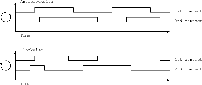 A shaft decoder module is required to convert this 2-bit Gray code into a 4-bit position count. The 4-bit position should be incremented every time the input changes from one state to another in a positive direction (e.g. from 00 to 01, or from 10 to 00). Similarly, the 4-bit position should be decremented every time the input changes from one state to another in a negative direction (e.g. from 00 to 10, or from 01 to 00). Components
Step 1 - shaft decoder to clockwise/anticlockwise signalsDesign task 1: Draw a state diagram to decode this movement. Generate two independent one-bit output, one bit pulsing high for one clock cycle when the shaft rotates one position clockwise, and the other for anticlockwise. Tip: make the next state the same as the current inputs. Design task 2: From the state diagram, create a truth table and derive equations for the inputs to D-type flip-flops. These equations will be used to implement a synchronous state machine (clocked from an independent free-running clock) inside a PAL. You need to produce equations for some of the 8 possible output pins 19 to 12. Use pins 2 and 3 as inputs. These equations should use variables p2 to p9 on the input side (representing the input pins) and p12 to p19 on the output side (representing output pins). NOTE: It is necessary to latch the outputs from the shaft encoder before applying them to your state machine in order to synchronize them. Make sure that the compiler is in registered mode. Your equations should therefore look something like this: P19 = p2 P18 = p3 P17 = p19 P16 = p18 P15 = <Some function of p16, p17, p18 and p19> P14 = <Some function of p16, p17, p18 and p19>This means that pin 19 is a latched version of pin 2 and pin 18 is a latched version of pin 3. Pins 17 and 16 are latched versions of pin 19 and 18 respectively, and should hold the state in your state machine. Pins 15 and 14 will be the 'count up' and 'count down' outputs, and should therefore be some function of the state (pins 17 and 16) and the latched inputs (pins 19 and 18). Implementation task 1: Now run your equations through the PAL compile. Read Appendix B on PALs and the PAL compiler if you are unfamiliar with them. The compiler should be running on a stand-alone PC connected to the programmer. Implementation task 2: Now connect your PAL to a rotary encoder and your two outputs to LEDs. Connect the clock to pin 1 and make sure that the output enable (pin 11) is connected to ground. To test your design start by setting the clock to 10Hz. Make sure that each LED flashes once as the rotary encoder is moved clockwise or anticlockwise. Step 2 - count clockwise/anticlockwise pulsesImplementation task: Use the clockwise/anticlockwise signals as up/down signals for the 74HC193 counter. Connect the output of the counter to the 7-segment display. Make sure the unused inputs of the 74HC193 and tied off appropriately. Optional Bonus StepTask: How could you make use of two 74HC193 chips to provide an 8-bit up/down counter? AssessmentTicking criteria: Write up your design and answer the following questions. Demonstrate that your rotary position counter works. Once your work has met the Common Ticking Criteria (see Introduction), get your work ticked by an assessor. Remember that you need to hand in this assessed exercise as part of your portfolio of work (see the Head of Department's notice). Questions
1. Why didn't we ask you to debounce the inputs from the rotary encoder? |
![]()