|
|
|||||
| Computer Laboratory
Lab 3 |
||
| Computer Laboratory > Course material 2004-05 > ECAD + Architecture Main Page > Lab 3 |
In the previous practical you wrote the driver for the display, and in labs 4-6 you will write ARM code to decode the Rugby signal. In this practical you will write Verilog to demodulate and remove noise from the Rugby MSF signal that we are transmitting via infrared, and to extract the time information that the ARM will later decode.
Because the IR receivers you are using are not DC coupled, the MSF signal is pulsed with a 50% duty cycle at about 60Hz. When there are pulses the MSF carrier is present. When there are no pulses the MSF carrier is off. You must recover the Rugby signal from this 60Hz carrier before trying to decode it. Remember that the IR detector is active-low, so its output will look like this:  where the square wave has a frequency of about 60Hz. In this practical you must flash an LED in time with the Rugby carrier. The IR beacons are on the floor in the middle of each decagonal table in the Intel Lab, with blue flashing lights. If you can't see them your demonstrators will point them out. You should write a module that turns this high-or-oscillating signal into a high-or-low output without any glitches. You will need a clean signal for the later stages of the decoding process. Ideas for doing this are presented below under 'Hints'. Don't forget that the IR detector is an asynchronous input so you will need to pass it through a synchroniser before using it to drive logic. (The 'debounce' module in lecture two of the ECAD notes would be a good place to start.) Testing this code is best done with the simulator built into Quartus. You will need this Vector Wave Form file that has a test input signal. It assumes that the module it is being used on will have two inputs (CLK,IR_IN) and one output (IR_OUT). Note that it contains a clock with a period 215 times as long as the clock on the board. This is to make the simulation run faster - you will need to slow the design down with a 15-bit counter when transferring your code from the simulator to the board, with some code like the following:
wire simulation = 1; // change this to 0 to run on the board
reg [14:0] slow_down;
always @(posedge CLK)
begin
  if (simulation || (slow_down==0))
  begin
    // insert your code here
  end
  slow_down = slow_down + 1;
end
To set up the simulator:
When you have this working, write a short wrapper that takes your code from the previous section and links its input to one of the general purpose inputs on the I/O board, and its output to a LED or output channel. Also wire the input to another LED or output channel, so you can check the IR reception. Program the EPXA1 board, and wire up the IR receiver module on the breadboard so that it is pointed straight up: the IR signal reflects quite strongly off the ceiling. The direct-wired LED should be dimmer than the output from your module, since it is driven by a signal with a 50% duty cycle.
You now need to write some more Verilog that will analyse the filtered signal returned from your module. The format of the MSF signal is described in the files on the datasheet page. It should have three outputs - the value of bit A, whether the frame represents a new minute, and a signal that will change state every time a new frame arrives. You will have to interface this module to the ARM in lab 6. There are only really 3 types of MSF signal you're interested in: 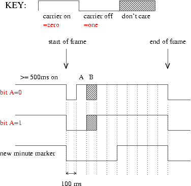
Examples of all three types of signal are clearly visible in the simulation data file (this is the same as the one given above). Notice particularly the "new minute" signal about one second into the file. Notice also that the diagram above gives the un-inverted, demodulated signal whereas the simulation file gives the inverted, modulated signal like the one you will receive from the IR detector, so a high signal in the diagram corresponds to the 60Hz oscillating signal, and low in the diagram above corresponds to a high input. If you want to test your decoder in the simulator, change the End simulation at option to a longer time period: it's probably a bad idea to use the whole file (42 seconds) as the simulation would take a while. Remember to regenerate the netlist, and remember to adjust your counter to cope with the slower clock. You will also want to add your output nodes in the waveform editor, the same way as you did for the first practical.
Questions
Ticking Criteria
Ticking procedure
|