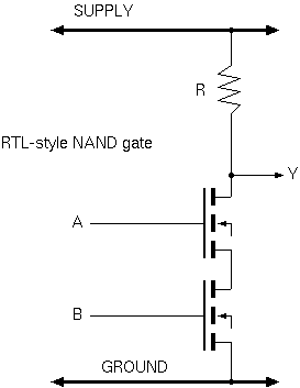
Resistor-transistor logic.
Note: This slide non-examinable.
Resistor-transistor logic (RTL) dissipates power while output is logic zero. This power is inversely proportional to R. R needs to be smaller for constant loading capacitance to get RC, the switching time constant smaller for higher-frequency operation.
Note, RTL pre-dates field effect transistors (fets). Bipolar transistors and thermionic valves were actually used. Also a pair of diodes might be used as the AND gate and a single transistor or valve used for the inverter stage.
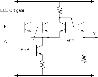
Emitter-coupled logic also uses an output load resistor that has the same power/speed trade off problem.
It goes faster than quivalent power RTL and TTL since it does not saturate the transistors and hence they recover faster.
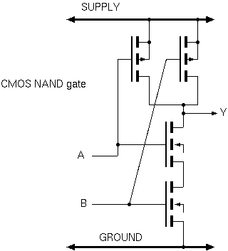
The breakthrough in CMOS was that one or other transistor was off while the output was static, hence zero static power consumption and energy use was entirely proportional to the load capacitance being charged on a zero-to-one output transistion.
Modern CMOS runs on lower supply voltages, meaning that transistors do not turn off entirely and hence static leakage exists, bringing back the problems mentioned above.