2016 note: This is an old demo and KiwiC does not internally work much like this any longer!.
On this web page we present a detailed worked example, showing how activations are used to walk the program flow graph.
In this example, the following C# program was compiled to .net CIL bytecode. The program simply prints a string to a parallel port. The parallel port operates a Two Phase Handshake whereby data is transferred on both edges of the strobe signal.
// Hello world written to parallel port.
using System; //NameSpace
public class parallel_port
{
    [Kiwi.OutputWordPort("")] static byte dout;
    [Kiwi.OutputBitPort("")] static bool strobe;
    [Kiwi.InputBitPort("")] static bool ack;

    public static void putchar(byte c)
	{
	  while (ack == strobe) Kiwi.Pause();
	  dout = c;
	  Kiwi.Pause();
	  strobe = !strobe;
	}

}

class test9
{
    public static void parallel_print(string s)
    {
      for(int i = 0; i<s.Length; i++)
           parallel_port.putchar((byte)s[i]);
    }

    public static void Main()
    {
	parallel_print("Hello World\n");
    }
}
// eof
The C# compiler generates the following assembler file: CIL Assembly Listing.
The CIL bytecode was read in by the prototype KiwiC compiler and converted from stack code to a sequential program in the internal virtual machine format.
The subroutine calling structure has been flattened at this point, so the main loop now directly mainipulates the parallel port I/O nets.
sensitivity=NONE
Listing: id=Main
0:test9_parallel_print_V_0 := 0;
1:Xgoto(test9/parallel_print/IL_0018, 16);
2:test9/parallel_print/IL_0007:
3:Xgoto(cilreturn115, 4);
4:cilreturn115:
5:Xgoto(parallel_port/putchar/IL_000a, 8);
6:parallel_port/putchar/IL_0005:
7:*APPLY:hpr_barrier();
8:parallel_port/putchar/IL_000a:
9:beq(!!(parallel_port_ack^parallel_port_strobe),parallel_port/putchar/IL_0005, 6)
10:parallel_port_dout := "Hello World\n"[test9_parallel_print_V_0]&mask(7..0);
11:*APPLY:hpr_barrier();
12:parallel_port_strobe := !parallel_port_strobe;
13:Xgoto(cilreturn116, 14);
14:cilreturn116:
15:test9_parallel_print_V_0 := test9_parallel_print_V_0+1;
16:test9/parallel_print/IL_0018:
17:beq( 10<=test9_parallel_print_V_0,test9/parallel_print/IL_0007, 2)
18:Xgoto(cilreturn117, 19);
19:cilreturn117:
20:return 0;
An overview of the `Greaves Hard Pause Mode' algorithm for mapping a program to an FSM is given in this section. The next section works through the above example, step by step. The Hard Pause Mode is used when the programmer wishes to maintain precise control over what work is done in which clock cycle. This is mostly useful for implementing synchronous protocols at net-level interfaces. The principle of the algorithm is that there is no compile-time state at a pause operation and every trajectory from one pause site to another has its behaviour 'rendered' in the output machine.

The input machine consists of an array of instructions addressed by a program counter. Each instruction is either an assignment (scalar or 1-D array), exit statement, built-in primitive or conditional branch. The expressions occurring in various fields of the instructions may be arbitrarily complicated, containing any of the operators and referentially-transparent library calls present in the input language, but their evaluation must be combinational. Pipelined operators need separate consideration: see later.
The output is a list of finite-state-machine edges, where edges have two possible forms:
  (g, v, e)
  (g, f, [ args])
where the first form assigns e to v when g holds and the second calls built-in function f when g holds. A second output is a success code which reports whether the program could be realised or whether additional clock cycles were inserted.
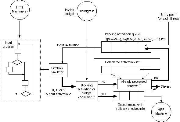
An optional, additional input, from the command line, can be a maximum unwind budget: a number of basic blocks (or other metric) to consider in any loop unwind operation. Where loops are nested or fork in flow of control, the budget is divided amongst the various ways. This can be used to give a form of Soft Pause Mode, where the work is automatically partitioned to clock cycles. Again, see later.
The central data structure is the pending activation queue where an activation has form
(p==v, g, S)consisting of a program counter (p) and its current value (v), a guard (g) and an environment list (S) that maps variables that have so far been changed to their new (symbolic) values. The guard is a condition that holds when flow of control reaches the activation.
Activations that have been processed are recorded in the completed activation queue and their effects are represented as edges written to the output queue. All three queues have checkpoint annotations so that edges generated during a failed attempt at a loop unwind can be rolled-back.
The pending activation queue is initialized with the entry points for each thread. Operation removes one activation and symbolically steps it through a basic block of the program code, after which zero, one or two activations are returned. These are either converted to edges for the output queue or added to the pending activation queue. An exit statement terminates the activation and a basic block terminating in a conditional branch returns two activations. A basic block is terminated with a single activation at a blocking native call, such as hpr_pause(). When returned from the symbolic simulator, the activation may be flagged as blocking, in which case it goes to the output queue. Otherwise, if the unwind budget is not used up the resulting activation(s) go to the pending queue. If the budget is used up, the system is rewound to the latest point where that activation had made some progress.
Activations are discarded instead of being added to the pending queue if they have already been successfully processed. Checking this requires comparison of symbolic environments. These are kept in a `close to normal form' form so that typographical equivalence can be used. A more-powerful proof engine can be used to check equivalence between activations, but there will always be some loops that might be unwound at compile time that are missed (decidability).
Operation continues until the pending activation queue is empty.
The generated machine contains an embedded sequencer for each input thread, with a variable corresponding to the program counter of the thread and states corresponding to those program counter values of the input machine that are retained after unwinding. However, the sequencer is no longer explicit; it is just one of the variables assigned by the FSM edges. When only one state is retained for the thread, the program counter variable is removed and the edges made unconditional.
The output edges must be compatible. Compatible means that that no two activations contain a pair of assignments to the same variable under the same conditions that disagree in value. Duplicate assignments of the same value at the same time are discarded. This checking cannot always be complete where values depend on run-time values, with array subscript comparison being a common source of ambiguity. Where incompatibility is detected, an error is flagged. When not detected, the resulting system can be non-deterministic.
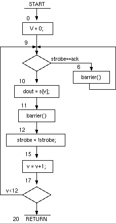
The flowchart for the Hello World example is drawn out below. The lables on the flowchart follow the program counter values in the listing above.

An initial activation is set at the entry point, having PC value zero, unconditional guard and a null substitution environment. This is placed in the pending activation queue. Every activation is prefix-tagged with its starting pc value, which is also zero for the entry point.
0:(pc==0, true, [])
The first (only) activation is taken from the pending queue and simulated. The actual implementation steps through basic blocks in one step, but in this illustration we step each statement.
After the first step, an assignment statement, there is a replacement activation.
0:(pc==9, true, [0/V])
This is compared for membership in the completed list. Since the list is empty, this activation is found not to have been processed before and is fed into the pending queue.
A conditional branch converts a single activations into two activations. After the branch at 9, the two new activations are
0:(pc==6, strobe==ack, [0/V])
0:(pc==10, strobe!=ack, [0/V])
0:(pc==10, strobe!=ack, [0/V])
0:(pc==11, strobe!=ack, [0/V, s[0]/dout])
11:(pc==12, true, [])
11:(pc==15, true, [!strobe/strobe])
11:(pc==17, true, [V+1/V, !strobe/strobe])
The behaviour of the barrier call at 11 is to flush the environment to the output queue and to reset the starting pc value and set the guard to hold unconditionally.
The branch at location 17 results in two activations. Note that the branch condition has been substituted out from the environment. The activations are:
11:(pc==9, V+1<12, [V+1/V, !strobe/strobe])
11:(pc==20, V+1>=12, [V+1/V, !strobe/strobe])
0:(pc==6, strobe==ack, [0/V])and the output is:
6:(pc==9, true, [])
There are now two new activations in the pending queue, both with pc value of 9. Neither of these has been run before and so both are run through the basic block at 9.
The first activation proceeds to the barrier at 12 as follows:
11:(pc==9, V+1<12, [V+1/V, !strobe/strobe])
11:(pc==10, V+1<12 && !strobe!=ack, [V+1/V, !strobe/strobe])
11:(pc==11, V+1<12 && !strobe!=ack, [V+1/V, !strobe/strobe, s[V+1]/dout])
11:(pc==12, true, [])
After the barrier, it is identical to an activation already processed, and so there is no further action. In the other branch, it proceeds to the barrier at 6 as follows:
11:(pc==9, V+1<12, [V+1/V, !strobe/strobe])
11:(pc==6, V+1<12 && !strobe==ack, [V+1/V, !strobe/strobe])
6:(pc==9, true, [])
The second activation proceeds from 9 to the barrier at 12 as follows:
6:(pc==9, true, [])
6:(pc==10, strobe!=ack, [])
6:(pc==11, strobe!=ack, [s[V]/dout])
11:(pc==12, true, [])
After the barrier, it is again identical to an activation already processed, and so there is no further action. It proceeds to the barrier at 6 as follows:
6:(pc==9, true, [])
6:(pc==6, strobe==ack, [])
6:(pc==9, true, [])
This is an exiting thread that encounters the return statement. It does so using the following activation:
11:(pc==20, V+1>=12, [V+1/V, !strobe/strobe])
The return statement is used to generate any combinational outputs from the design. There are none in this example, but if the root method had a return value or output arguments then values held in the environment at a return statement are copied to these nets. For a pause-less design, fully-combinational logic is generated.
As shown in the RTL listing below, a $finish statement can also be generated if desired.
The results are generated by the barrier statements.
The results from this elaboration are listed here:
0:(pc==6, strobe==ack, [0/V])
0:(pc==11, strobe!=ack, [s[V]/dout])
11:(pc==6, strobe==ack, [])
11:(pc==11, V+1<12 && !strobe!=ack, [V+1/V, !strobe/strobe, s[V+1]/dout])
11:(pc==20, V+1>=12, [V+1/V, !strobe/strobe])
The output sequencer transfers between old and new PC values based on the guard conditions of the results.
The updates to state variables are generated from the environment results guarded by the conjunction of the guard condition and the PC being at its start state.
There are three different PC values in these results, so the output sequencer requires three states. A final renumbering phase packs the disjoint PC values into a continuous range (or one-hot if wanted).
The Verilog RTL was generated as listed below. In this example, the output was not simplified, so that the individual results from the compilation steps are visible as individual Verilog assignments.
// CBG Orangepath HPRLS System
// Verilog output file generated at Tue Mar  4 11:09:15 GMT 2008
// Kiwic: HPR Orange IL/.net front end: Version alpha 11 : 2-Mar-08
// -root parallel_port;test9;test9.Main -vnl PARP.v


module PARP(clk, reset, parallel_port_ack, parallel_port_dout, parallel_port_strobe);
  input clk;
  input reset;
  input parallel_port_ack;
  output [7:0] parallel_port_dout;
  reg [7:0] parallel_port_dout;
  output parallel_port_strobe;
  reg parallel_port_strobe;
  reg [1:0] pcnet119p;
  parameter str99 = "Hello World\n";
  integer test9_parallel_print_V_0;

  always @(posedge clk) begin
          case (pcnet119p)

          0:  begin if (reset) pcnet119p <= 0;
                 if (parallel_port_ack==parallel_port_strobe && !reset) pcnet119p <= 2;
                 if (!(parallel_port_ack==parallel_port_strobe) && !reset) pcnet119p <= 1;
                 if (parallel_port_ack==parallel_port_strobe) test9_parallel_print_V_0 <= 0;
                 if (!(parallel_port_ack==parallel_port_strobe)) test9_parallel_print_V_0 <= 0;


                 if (!(parallel_port_ack==parallel_port_strobe)) parallel_port_dout <= str99[0]&8'hFF;

                  end
          1:  begin if (reset) pcnet119p <= 0;
                 if (parallel_port_ack==!parallel_port_strobe && test9_parallel_print_V_0<9 && !reset) pcnet119p <= 2;
                 if (parallel_port_ack==!parallel_port_strobe && test9_parallel_print_V_0<9) parallel_port_strobe <= !parallel_port_strobe;
                 if (parallel_port_ack==!parallel_port_strobe && test9_parallel_print_V_0<9) test9_parallel_print_V_0 <= test9_parallel_print_V_0+1;
                 if (!(parallel_port_ack==!parallel_port_strobe) && test9_parallel_print_V_0<9) parallel_port_strobe <= !parallel_port_strobe;
                 if (!(parallel_port_ack==!parallel_port_strobe) && test9_parallel_print_V_0<9) test9_parallel_print_V_0 <= test9_parallel_print_V_0+1;
                 if (!(parallel_port_ack==!parallel_port_strobe) && test9_parallel_print_V_0<9) parallel_port_dout <= str99[test9_parallel_print_V_0+1]&8'hFF;
                 if (14<test9_parallel_print_V_0) parallel_port_strobe <= !parallel_port_strobe;
                 if (14<test9_parallel_print_V_0) test9_parallel_print_V_0 <= test9_parallel_print_V_0+1;
                 if (14<test9_parallel_print_V_0) $finish(0);


                  end
          2:  begin if (reset) pcnet119p <= 0;
                 if (!(parallel_port_ack==parallel_port_strobe) && !reset) pcnet119p <= 1;
                 if (!(parallel_port_ack==parallel_port_strobe)) parallel_port_dout <= str99[test9_parallel_print_V_0]&8'hFF;

                  end endcase
           end
endmodule
The Verilog was placed in a testbench that provides clock and reset and which generates an ack signal from a delayed and inverted version of the strobe signal.
module SIMSYS();
   reg clk, reset;
   initial begin reset = 1; clk = 0; # 50 reset = 0; end
   always #1000 clk = !clk;
   initial #200000 $finish;

   wire[7:0] dout;
   wire ack, strobe;
   PARP dut(clk, reset, ack, dout, strobe);

   // Feed ack from strobe after a delay.
   assign #220 ack  =  !strobe;

   always @(strobe) $display("Char %c", dout);
endmodule
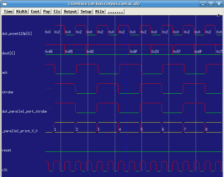
The following screen shot shows the nets being traced in the simulator:

The console output from the simulator was:
Char H
Char e
Char l
Char l
Char o
Char
Char W
Char o
Char r
TBD ...
Another common requirement is the allocation of work to clock cycles fully automaticly. This is generally needed for acceleration of scientific algorithms. Such code will not contain pause statements inserted by the user. Details of such algorithms for Kiwi will be documented elsewhere. But the Hard Pause Mode algorithm can be made to serve for this purpose. Either a pre-processing stage can insert pause statements in the abstract syntax tree at appropriate points, or these can be virtually inserted on-the-fly where any activation that is augmented beyond a certain complexity, as measured by a heuristic, is terminated just before or after that augmentation.
This web page shows the steps used in an example where speculative loop unwind was not needed. The full algorithm attempts to unwind loops that do not contain pauses, up to a user-set limit, and keeps the result if a closure was reached, otherwise it uses the result from the last successful advance. The full algorithm also inserts a pause statement between array operations with undecidable subscript comparisons. Where a pause was introduced that does not correspond to an input pause site, the algorithm reports this. This will be a failure in general, since if there were flexibility over where the pause statements are placed, the Soft Pause Mode should probably have been in use.
Updated March 2008. UP.