HPR System Integrator is an open-source EDA tool that uses the HPR L/S library. It is primarily used to generate top-level circuit structures around logic blocks from diverse sources. However, it can be used with IP blocks from any source, provided they are annotated with a small number of IP-XACT extensions regarding purpose, area, latency and throughput. These extensions should accord with the cards schema.
HPR System Integrator automatically instantiates Verilog RTL blocks created by KiwiC or sourced from third parties, provided they are accompanied with an XML meta-data file that indicates their primary features. Its output is a structural RTL netlist plus report files. Alternatively, its output is an IP-XACT design document that will instruct a third-party tool to form the structural netlist. Many EDA systems will obey such a design document.
Working draft white paper: DOWNLOAD PDF
(The tool is also described in a dedicated section in the back of the Kiwi user manual.)
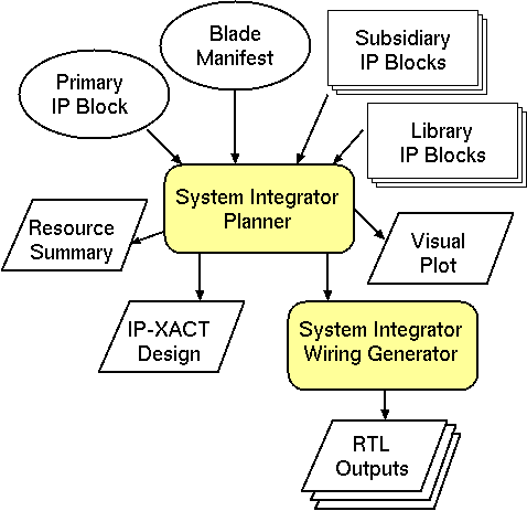
The general flow for the tool is illustrated in this figure. Its inputs are the name of a primary IP block for the top-level, a search path for lookup of the so-called subsidiary and auxiliary IP blocks, and a description of the target platform described in a file blade-manifest.xml. The tool operates in two stages. The first is a planner that makes floorplanning and memory layout decisions and instantiates subsidiary and auxiliary blocks as needed. The resulting high-level design is written out as an IP-XACT design report, a graphical plot and a human-readable report that tabulates utilisation metrics. The second stage compiles the design to a structural netlist. This writes out a master RTL file for each FPGA.
The blade manifest lists the number of FPGAs available on the platform, describing their size, interconnection pattern and hardened IP ports and capabilities. It is an XML file crafted by hand or using an XML editor.
Separate and incremental compilation is needed in all large projects to handle scale, component reuse, revision control and is the basis for project management. It can also be a basis for parallelism. Here we use it as a mechanism to trade execution time against silicon space.
Moreover, the default approach of Kiwi is one of 'flattening' where the leaf components are largely replicated at each instantiation within a hierarchic design. KiwiC reuses ALUs and local variable registers in both the spatial and time domains, but tends to generate the largest and fastest circuit it can, subject to ALU instance count limits per thread set in the recipe. For larger designs, to manage complexity, it is desirable to designate subsystems for separate compilation.
Multi-FPGA designs require separate runs of the FPGA logic synthesis tools for each FPGA.
The ability to use separately-compiled components is also needed as a black box import mechanism for third-party IP blocks.
Finally, the controlling FSMs for separately-compiled components, if they have them, are intrinsically separate and their states are re-used for each invokation which contrasts strongly with the approach for method calls within a single compilation whose control flow is expaneded in-line.
In some design styles, subsystems can also best be placed in a server pool with dynamic load balancing. Design-time manual control sets the number of instances generated. KiwiC will share such server instances in the time domain rather than instantiate as many as it needs (subject to ALU count limits).
The IP-XACT schema provides much of the information needed to import a hardware IP block. Beyond providing the block name and version number, it gives a full description of the net-level interface and any TLM interfaces in higher-level models. The precision of the implemented function is manifested by the bit-widths of the busses.
Hence the System Integrator mode of compilation, illustrated below for the peered instances, is readily supported without extensions. Afterall, this is the primary use today for IP-XACT.
But further information is needed for replication and schedulling of such blocks in an HLS flow. The additional information needed is:
There are two main module instantiation styles: IP blocks can be instantiated as peers or with hierarchy.
Each instanced block needs to have both a C# implementation and an RTL implementation packaged with an IP-XACT wrapper. The RTL and IP-XACT may have been generated by earlier runs of KiwiC or else may have been created by hand or have come from a third party. The C# version is required for two reasons: 1. so that the instantiating C# file will compile without a missing class error, and 2. so that the the system as a pure dotnet design in WD (workstation development) environment. Only a stub implementation (null method bodies) is needed for C# compilation to succeed. And for the dotnet run, only a high-level behavioural model is needed in the C# when the real implementation comes from elsewhere, such as when it is hardened IP like the NetFPGA CAM.
Peer instancing skeleton example:
  RAM r = new RAM(...);     // Create peer instances
  CPU c = new CPU(...);     //
  IO  i = new IO(...);      //
  c.axi_m0.bind(r.axi_s0);  // Establish wiring between them.
  c.axi_m1.bind(i.axi_s0);  // bind is provided by SystemCsharp TLM.
Hierarchic instancing skeleton example:
  [Kiwi.Remote(...)] ALU a = new ALU(...);

  int foo(int x, int y) = { return x * a.f1(y/121); }
KiwiC will compile each of the above examples and generate its outputs (IP-XACT, RTL and SystemC).
In the peer instancing example, each of the three instantiated components is defined as a class that is itself marked up with the Kiwi.Remote() attribute. In the hierarchic example, the attribute is instead applied to the instance. Also, in the hierarchic example, the ALU instance may actually be placed outside the rendered containing RTL with additional top-level ports provided for wiring it up.
Note that the ALU in the hierarchic example might typically be stateless and hence replicatable. If so, its invokation will be completely on a par with the multiplier and divider instances also needed for method foo. The HLS binder will decide how many instances of it to make and the HLS scheduller will factor in the appropriate fixed pipelining delay or variable delay and handshake nets.
The HPR System Integrator writes a report file containing tables of results. This is the routed-connections table after the insertion of bridges and concentrators:
Start of aux report HPR System_Integrator
Concentrated and Bridged Connections
*----------------------------+-----------+-------------------+---------------------------------------------------------------+----------------------------------------------------+---------------*
| Name                       | Link Type | Channel Kind      | Initiator                                                     | Target(s)                                          | Compatibility |
*----------------------------+-----------+-------------------+---------------------------------------------------------------+----------------------------------------------------+---------------*
| chassoc944.LN.0.NY.MUXi0   | 1-to-1    | axi4/1.0          | chip1 chassoc944_adt_near_0  port-left axi4                   | chip1 axi4216_mux  childport0 axi4                 |               |
| axi4214.MUX.MUXi1          | 1-to-1    | axi4/1.0          | chip1 axi4214_mux  focus axi4                                 | chip1 axi4216_mux  childport1 axi4                 |               |
| axi4216.MUX                | 1-to-1    | axi4/1.0          | chip1 axi4216_mux  focus axi4                                 | chip1 ONE-to-TWOlanding  PortS axi4                |               |
| axi4216.DEMUX              | 1-to-1    | axi4/1.0          | chip2 ONE-to-TWOlanding  PortM axi4                           | chip2 axi4216_demux  focus axi4                    |               |
| chassoc944.LF.0.FX.DEMUXi0 | 1-to-1    | axi4/1.0          | chip2 axi4216_demux  childport0 axi4                          | chip2 chassoc944_adt_far_0  port-left axi4         |               |
| axi4214.DEMUX.DEMUXi1      | 1-to-1    | axi4/1.0          | chip2 axi4216_demux  childport1 axi4                          | chip2 axi4214_demux  focus axi4                    |               |
| chassoc938.LN.0.NY.MUXi0   | 1-to-1    | axi4/1.0          | chip1 chassoc938_adt_near_0  port-left axi4                   | chip1 axi4214_mux  childport0 axi4                 |               |
| chassoc942.LN.0.NY.MUXi1   | 1-to-1    | axi4/1.0          | chip1 chassoc942_adt_near_0  port-right axi4                  | chip1 axi4214_mux  childport1 axi4                 |               |
| chassoc938.LF.0.FX.DEMUXi0 | 1-to-1    | axi4/1.0          | chip2 axi4214_demux  childport0 axi4                          | chip2 chassoc938_adt_far_0  port-left axi4         |               |
| chassoc942.LF.0.FX.DEMUXi1 | 1-to-1    | axi4/1.0          | chip2 axi4214_demux  childport1 axi4                          | chip2 chassoc942_adt_far_0  port-right axi4        |               |
| chassoc944.LN.0.NX         | 1-to-1    | loadstore10/1.0   | chip1 fortopprimaryIPblock424  loadstore10-m-port loadstore10 | chip1 chassoc944_adt_near_0  port-right loadstore\ |               |
|                            |           |                   |                                                               | 10                                                 |               |
| chassoc944.LF.0.FY         | 1-to-1    | loadstore10/1.0   | chip2 chassoc944_adt_far_0  port-right loadstore10            | chip2 forfortopprimaryIPblock42410  offchip-memor\ |               |
|                            |           |                   |                                                               | y-service-port loadstore10                         |               |
| chassoc942.LN.0.NX         | 1-to-1    | directorate12/1.0 | chip1 *top-primary-IP-block*  dir12port directorate12         | chip1 chassoc942_adt_near_0  port-left directorat\ |               |
|                            |           |                   |                                                               | e12                                                |               |
| chassoc942.LF.0.FY         | 1-to-1    | directorate12/1.0 | chip2 chassoc942_adt_far_0  port-left directorate12           | chip2 fortopprimaryIPblock418  dirshim-directorat\ |               |
|                            |           |                   |                                                               | e12-port directorate12                             |               |
| chassoc940                 | 1-to-1    | bram33/1.0        | chip1 *top-primary-IP-block*  bram33port bram33               | chip1 fortopprimaryIPblock420  BRAM-slave-port br\ |               |
|                            |           |                   |                                                               | am33                                               |               |
| chassoc938.LN.0.NX         | 1-to-1    | loadstore10/1.0   | chip1 *top-primary-IP-block*  loadstore10m-port loadstore10   | chip1 chassoc938_adt_near_0  port-right loadstore\ |               |
|                            |           |                   |                                                               | 10                                                 |               |
| chassoc938.LF.0.FY         | 1-to-1    | loadstore10/1.0   | chip2 chassoc938_adt_far_0  port-right loadstore10            | chip2 fortopprimaryIPblock422  offchip-memory-ser\ |               |
|                            |           |                   |                                                               | vice-port loadstore10                              |               |
| chassoc936                 | 1-to-1    | subsa0/1.0        | chip1 *top-primary-IP-block*  subsa0-master-port0 subsa0      | chip1 fortopprimaryIPblock424  subsa0-slave-port \ |               |
|                            |           |                   |                                                               | subsa0                                             |               |
*----------------------------+-----------+-------------------+---------------------------------------------------------------+----------------------------------------------------+---------------*
End of aux report HPR System_Integrator
Design attempt: count=16 zones=chip1, chip2.   cost=132.3
Another report table is the contents of each FPGA chip (layout zone):
Start of aux report HPR System_Integrator
Percentage utilization in chip1 is 5.9 %
End of Trial Floorplan: Blocks in zone chip1
*-------------------------------+-------------------------+-----------------------------------------------------------------------+---------------------------*
| Block Kind                    | Block Instance Name     | Block port domains                                                    | Area                      |
*-------------------------------+-------------------------+-----------------------------------------------------------------------+---------------------------*
| concen_2_axi4_MUX             | axi4214_mux             | DP_unbound, DP_unbound, DP_unbound                                    | 50.40 NAND2-equivalents   |
| concen_2_axi4_MUX             | axi4216_mux             | DP_unbound, DP_unbound, DP_unbound                                    | 50.40 NAND2-equivalents   |
| adaptor-loadstore10-axi_puber | chassoc938_adt_near_0   | DP_unbound, DP_unbound                                                | 40.30 NAND2-equivalents   |
| adaptor33-axi_unter           | chassoc942_adt_near_0   | DP_unbound, DP_unbound                                                | 40.30 NAND2-equivalents   |
| adaptor-loadstore10-axi_puber | chassoc944_adt_near_0   | DP_unbound, DP_unbound                                                | 40.30 NAND2-equivalents   |
| primex                        | *top-primary-IP-block*  | DP_directing, DP_memory_service, DP_memory_service, DP_memory_service | 844.10 NAND2-equivalents  |
| example_BRAM44                | fortopprimaryIPblock420 | DP_directing                                                          | 2814.00 NAND2-equivalents |
| primsubs55                    | fortopprimaryIPblock424 | DP_directing, DP_memory_service                                       | 844.10 NAND2-equivalents  |
| TOTAL                         |                         |                                                                       | 4723.90 NAND2-equivalents |
*-------------------------------+-------------------------+-----------------------------------------------------------------------+---------------------------*


Percentage utilization in chip2 is 1.6 %
End of Trial Floorplan: Blocks in zone chip2
*--------------------------------+------------------------------+------------------------------------+---------------------------*
| Block Kind                     | Block Instance Name          | Block port domains                 | Area                      |
*--------------------------------+------------------------------+------------------------------------+---------------------------*
| concen_2_axi4_DEMUX            | axi4214_demux                | DP_unbound, DP_unbound, DP_unbound | 50.40 NAND2-equivalents   |
| concen_2_axi4_DEMUX            | axi4216_demux                | DP_unbound, DP_unbound, DP_unbound | 50.40 NAND2-equivalents   |
| adaptor-loadstore10-axi_punter | chassoc938_adt_far_0         | DP_unbound, DP_unbound             | 40.30 NAND2-equivalents   |
| adaptor33-axi_uber             | chassoc942_adt_far_0         | DP_unbound, DP_unbound             | 40.30 NAND2-equivalents   |
| adaptor-loadstore10-axi_punter | chassoc944_adt_far_0         | DP_unbound, DP_unbound             | 40.30 NAND2-equivalents   |
| axi_dir_shim                   | fortopprimaryIPblock418      | DP_directing, DP_directing         | 800.10 NAND2-equivalents  |
| offchip-memory-service-shimr   | fortopprimaryIPblock422      | DP_unbound, DP_unbound             | 140.30 NAND2-equivalents  |
| offchip-memory-service-shimr   | forfortopprimaryIPblock42410 | DP_unbound, DP_unbound             | 140.30 NAND2-equivalents  |
| TOTAL                          |                              |                                    | 1302.40 NAND2-equivalents |
*--------------------------------+------------------------------+------------------------------------+---------------------------*
End of aux report HPR System_Integrator
Design attempt: count=16 zones=chip1, chip2 cost=132.3
The System Integrator generates a graphical plot like this early example:
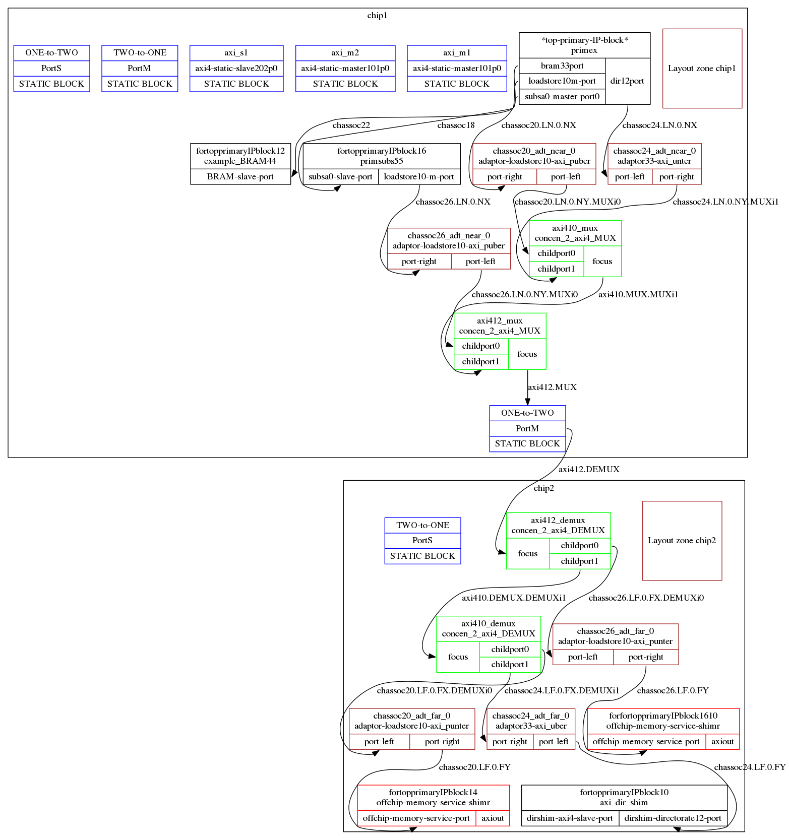
The primary and subsidiary I/P blocks are in black. Concentrators are in green. Adaptors are in brown.
Kiwi defines that if any subsystem stops with an abend syndrome code, this must be passed up through parent modules to the substrate wrapper. And all modules must halt at that instant so PC values can be collected.
An example of glue logic being inserted by System Integrator is when it must collect these abend syndromes and PC values from each instantiated module and combine them into a larger abend code and to halt the composite when any component abends.
In the peer instancing example, the KiwiC front end will invoke the System Integrator function of the HPR library that underlies Kiwi.
System Integrator is a simple IP-XACT-driven wiring generator with support for:
Apart from syndrome and PC collection, another example, at the moment, is that KiwiC generates HFAST load/store ports but the Zynq platform requires these to be adapted to AXI. This can either be done automatically by System Integrator or by using the IP Integrator GUI within Vivado.
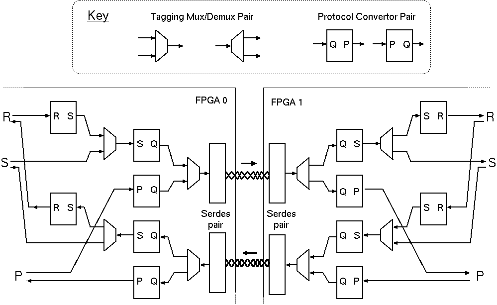
Inter-FPGA bridge structure: typical setup. The SERDES instances,
as described manually in the blade manifest, are utilised by the System Integrator's
instantiation of protocol adaptors and concentrators as required.
As illustrated by the SERDES pair in the above Figure. inter-FPGA bridges are bi-directional and have four ports for binding by the System Integrator as it creates an inter-FPGA network. The two ends of each simplex channel have the same domain name, but the bandwidth and latency for the two channels can be described differently in the associated IP-XACT description.
Each of the four bus interfaces is AXI streaming with a specified word width, giving the lossless FIFO paradigm. Each direction of the pair is kept matched by the System Integrator, as it adapts the hardware resource to its needs. The adaption steps are just the same as may be freely used elsewhere in the assembly: they are inserting a protocol adaptor pair on each side or inserting a concentrator pair consisting of a tagging mux and an inverse de-multiplexing component that processes and removes the tags. There is a set of standard protocol adaptors corresponding to all basic method signatures of up to 3 arguments with and without a result in our standard distribution. Others can be created by hand as needed and added to the library, or they can be macro-generated on demand in the future. Glue logic for these purposes can also be synthesised from a non-deadlocking, data-conserving product of protocol state machines by known techniques, Greaves-Nam.
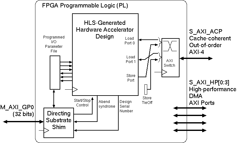
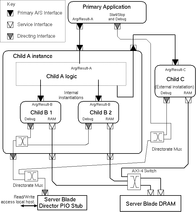
A basic instantiation on Zynq-like platform. Programmed I/O serves the
director port with an AXI slave and two in-order load ports
and one store port are multiplexed onto an AXI-4 port for out-of-order service.
The Figure shows a typical basic configuration with no subsidiary IP blocks. It shows three simplex ports that need connecting to main memory. Our HLS tool generates half-duplex load/store ports and simplex load and store ports. The more ports it generates, the greater the potential bandwidth to main memory there is. In the Figure, two ports are load-only and one is store-only. We use this approach since each simple port is a load/store station with one transaction outstanding at a time that must be served in order. But their multiplex will have multiple outstanding transactions that can be served out-of-order provided replies are routed back to originators correctly. This is standard behaviour for AXI-4 ports. (Our HLS tool actually generates ports that are a little simpler than AXI-lite, but these are adapted to AXIb-lite using automatically-deployed, lightweight bus adaptors that are not shown in the figure for clarity and the concentrating switch accepts AXI-lite on the left-hand side and delivers full AXI with transaction tags on the right.)
Types of Component (IP block) Understood by System Integrator.
| Primary IP Block | A top-level component of the design, typically the HLS result from the main application, that embodies an algorithm or processes and generates work for all the other components. |
| Subsidiary IP Block | An IP-block with slave ports that performs an operation. Examples are RAMs, ALU s and HLS outputs from earlier parts of an incremental compilation process. Subsidiary IP blocks may be nailed (statically-instantiated) to a given physical FPGA with fixed instance count, such as a DRAM controller, or may be portable and dynamically deployable on any die. |
| Inter-FPGA bridge | Statically-instantiated connection between two named FPGAs. This is the one component that is allowed to have its ports in different layout zones. |
| Aggregator | For combining ports (typically memories) into a logical entity. These demultiplex based on a chop of an address field. |
| Concentrator Pairs | Consisting of a tagging muxer and an associated demuxer. The tags are created by our tool and hardwired onto input ports during instantiation and demultiplexing is based on the tag values. |
| Protocol Adaptor | For converting between bus standards. |
| Zone id generator | Provides a single, static, broadcast, always-ready, output port number containing the current chip or layout zone number. |
Where the available word width is sufficient to carry the data and the tag, the auxiliary IP blocks are commonly purely combinational for most bus standards. Hence their implementation logic is trimmed greatly and interwoven with the adjacent primary and subsidiary blocks duing FPGA logic synthesis,
Broadcast connections are only currently supported for and used for static constant values, such as a zone-ID tie off that gives the current layout zone (aka FPGA) number when needed for tagging data. Everything else is a one-to-one connection that is only fanned-in or out by instantiating concentrators and aggregators.
Protocol adaptors contain data-conserving logic that adapts between two different protocols or variants of a common protocol that might have a different data buse width or other variation in strict metainformation.
Protocol adaptors have two ports, one being a target and the other an initiator. It is usual for the adaptors to be made available in the library in handed pairs, so either protocol can be the initiator.
When a protocol adaptor is instantiated, it is given a fresh domain variable that is allocated to both ports.
Warshall's algorithm is also applied to find bridged routes between layout zones.
Warshall's algorithm is also applied to protocol adaptors in the library, to see what can be connected to what in principle and the best pattern of adaptors, giving each adaptor a unit cost at this time. We must avoid building wandering chains that convert backwards and forwards between protocols, but as Warshall considers each protocol a node in a multi-hop journey, it will only instantiated at most one of each type of adaptor in a path.
An example cost matrix:
Protocol Adaption Cost Matrix
*---------------+-------------+---------------+----------+----------*
| From/To       | loadstore10 | directorate12 | axi3-D32 | axi4-D32 |
*---------------+-------------+---------------+----------+----------*
| loadstore10   | 0           | 2             | 2        | 1        |
| directorate12 | 2           | 0             | 2        | 1        |
| axi3-D32      | 2           | 2             | 0        | 1        |
| axi4-D32      | 1           | 1             | 1        | 0        |
*---------------+-------------+---------------+----------+----------*
...
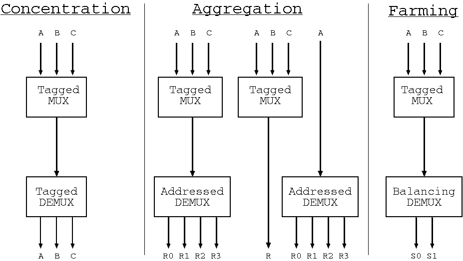
Three forms of multiplexing/demultiplexing where the demultiplexors
respectively uses tags, addresses and utilisation to make a routing decision.
The Figure shows three use cases involving tagged multiplexing and differing demultiplexing approaches. The arrows in the Figure indicate direction of initiation, but each underlying bus can normally carry data in either direction according to the whether read-style or write-style operations are currently being conveyed.
The left of the Figure shows straightforward concentration, where multiple logical channels are conveyed over a shared physical channel. A tagging multiplexor is matched with a detagging demultiplexor. The tags inserted at the top are removed at the bottom and are private to the configuration. This configuration provides perfect data conservation with respect to the mulitplexed channels from the point of entry at the top to the point of exit at the bottom.
The centre of the Figure shows shared access to a logical address space by a number of initiators where the address space is served by an aggregation of physical memory resources. The demultiplexor operates using address ranges. The multiplexor still inserts tags, but this time these are removed again also by the multiplexor. These tags are only examined by the multiplexor that created them: it removes them when the result is forwarded upwards to the originator. The tags are conveyed opaquely within all lower components. Two degenerate forms of the aggregation configuration arise: 1.~when there is only a single client for an aggregated resource, the multiplexor is not needed; and 2.~when the resource is monolithic the demultiplexor is not needed.
The right of the Figure illustrates the server farm configuration, that again uses a tagging multiplexor, but the demultiplexor operates on a load-balancing basis. The server farm is not currently natively supported by HPR System Integrator. Instead, the user must implement this paradigm by writing their own implementations of the multiplexor and demultiplexor. This is easy to do in C# for synthesis to RTL by KiwiC. If the C# is marked up for separate synthesis of the relevant components, the HPR System Integrator will then assemble the system, treating the farming blocks as subsidiary IP blocks to be assembled as normal. An example will be placed here ... TBD.
A connection between two components is valid when all of the following conditions hold:
The domain unifier operates over equivalence classes that contain at most one domain constant and any number of domain variables that are unified to that constant or just to each other when a domain constant is not present.
When a protocol adaptor is instantiated, it is given a fresh domain variable that is allocated to both ports.
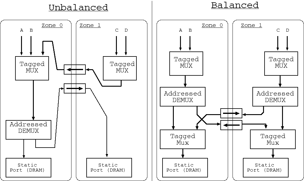
Illustration of non-uniform memory access designs: Left is the typical currently-generated style and right is a preferred style for the future.
It is desirable for traffic to take the shortest route between layout zones. The HPR System Integrator implements Warshall's algorithm to find available routes and to price design solutions that use them. However, the Figure shows, on the left, the typical structure that arises when static resources in two different zones are aggregated and then shared by clients where the clients (A, B, C and D) are also distributed over the zones.
The right-hand side of the figure illustrates a preferred design that is typically exploited in non-uniform memory architectures (NUMA). Although this has a little more logic, the average access latency for Zone1 is improved.
The HPR System Integrator operates by first creating the required data paths as a rats' nest without regard to layout zone. It then inserts bridges and concentrators as it maps that network onto the layout zones. This leads to the left-hand style of design. To achieve the preferred design, greater smartness is needed: a spatially aware design is needed from the outset. We aim to address this in a subsequent release of the tool.
It is interesting to examine whether HPR System Integrator can be said to be synthesising a Network-on-Chip (NoC).
Although there may be no absolute definition of what constitutes a NoC, the following defining principles can be identified:
The HPR System Integrator will make a custom mesh network as it instantiates concentrators to exploit shared inter-zone bridges. So it does sometimes generate a NoC using the `sharing' principle. Where the inter-zone bridges are arranged just as a physical ring, then the resulting network is a ring network (being a degenerate form of mesh). The ring is bi-directional or uni-directional, in terms of instantiation, according to the same property in the pattern of the available bridges. But each bridge is bi-directional in data terms, in that responses are carried in the reverse direction over the bridge that carried the request. Overall, there is currently no route diversity.
In the future, for large FPGAs, it is sensible perhaps to divide them into several layout zones, perhaps with fluid boundaries where area can be vired between zones. It will then be neccessary to instantiate inter-zone bridges in the blade manifest between these zones. Such bridges will be nothing more than point-to-point wiring, which will be totally reified by the back-end logic synthesis tool, so there is no run-time overhead. The advantage is that the pattern of concentrators will closer resemble a fine-grained NoC and the generated wiring will resemble ...
Various other System Integrator tools are available. Examples are Socrates from ARM, IP Integrator from Xilinx, Qsys from Altera, Kactus2 from TU Tampere, and Magillem. Most prior tools are GUI-based editors. HPR System Integrator is designed to be fully automatic. In the future it will use a Genetic Algorithm or other AI/Planner solution, but at the moment it takes the best of 50 or so runs based on pseudo-random constructive placement...
... page (was) under construction June/July 2017. Further work is under the Kiwi-Axelgraph heading LINK.
EOF.