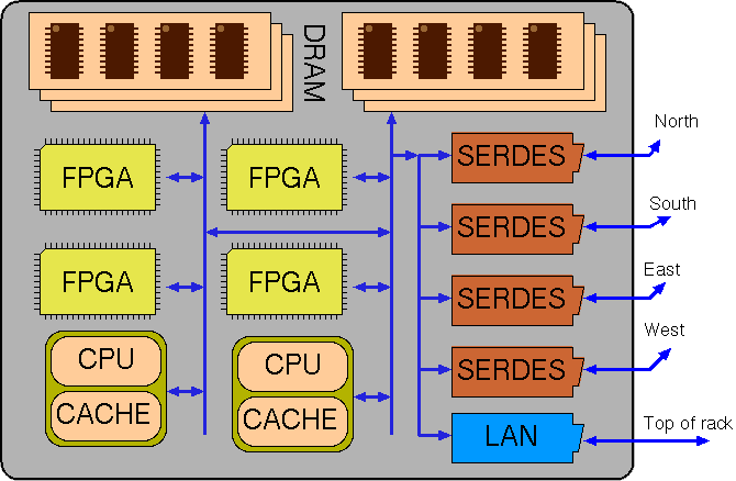
Nominal structure for a single blade of a cluster (SSD not shown).
Kiwi-Axelgraph2 is a multi-blade co-synthesis project implemented as two source-to-source refactoring procedures on dotnet bytecode along with a run-time library (the Axlegraph substrate).
We mainly address the situation where code is small and can easily be replicated over nodes whereas data is big and must be sharded over nodes with low replication counts or else served from secondary storage (from a fileserver or local SSD) (streaming or random access).
Although code may be small, the best target may be FPGA or CPU, so as well as automatically deciding on code and storage projections, we make automatic partition between RTL and C++ output (co-synthesis) with automatic insertion of communication primitives or shared memory structures.
We describe a set of semantics-preserving rewrite rules that are applied to the body of a fixed-point iteration so that it better maps to parallel hardware. An automated proof technique enables loop-carried constraints to be relaxed. The rules adjust where data is stored and how much it is replicated. They adjust the nesting order, direction and skewing of loops in the traditional way, but with additional data dependence relaxations. For graph processing algorithms, the rules can often transform between node-centric and edge-centric implementations by exploiting the commutibility of effects such as increment and bit set and associativity of operators such as addition and max. We demonstrate correct operation for seven standard graph algorithms and report on both FPGA and CPU implementations. Our implementation for dotnet is open source (link to be added here).
Keywords: Pregel, HLS, LINQ, FPGA.
We describe a planner/mapper tool that operates on dotnet bytecode. The bytecode is normally generated from C# programs and can be run directly on the mono platform (and Windows as well). The planner/mapper projects the code to a multi-blade parallel form by automatic insertion of communications primitives. A blade is here defined as a shared-memory computing entity with one or several banks of DRAM in a single address space and any number of CPU and FPGAs that use this memory. The system as a whole contains a number of such blades, described in a blade manifest xml file, and a fileserver.
The planner makes partitioning decisions both for where data is stored (including mirroring) and where computations are performed. The resulting plan is then projected into a number of dotnet bytecode files that can be interpreted for low performance or compiled to X86/ARM machine code or FPGA logic (via Kiwi) for high performance.
Nominal structure for a single blade of a cluster (SSD not shown).
The target execution environment is a network of blades in a cloud server farm. Each blade has CPU, FPGA and DRAM. It may also have Flash memory. Blades are locally interconnected in subnetworks using Gbps serdes links to form a clusters. Blade clusters are interconnected by top-of-rack Gbps switched Ethernet.
The following picture shows the general arrangement of a datacentre with a development workstation
that runs the compiler and software development tools. The generated code is held on the fileserver
along with the application data. There are many racks of server blades.
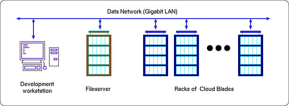
Generic Kiwi-Axelgraph Cloud View..
The following flow diagram shows the Kiwi-Axelgraph software program development and execution flows.
A complex program needs to be orchestrated in time and space, making access to the cloud
resources while being fair to other resource users. It must be accompanied with a resource budget
and execution priority to describe the intended time/space trade off.
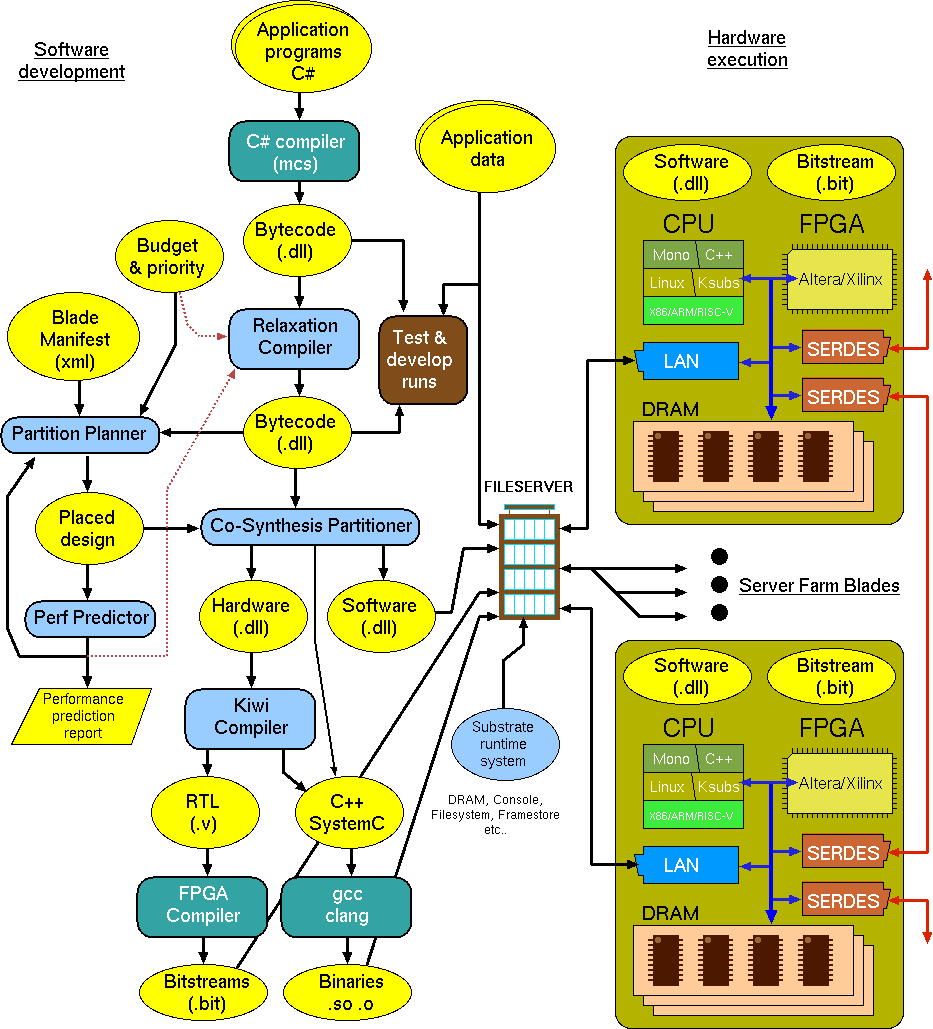
Axelgraph program development and execution flows..
Flow is concentrated on the networked fileserver. User data is held on the fileserver and also mirrored and created in the DRAM and SRAM of the farm blades. Programs are also held on the fileserver.
Application programs are written in C# and compiled as normal. This provides low performance execution for test and development.
The hardware structure and number of the available cloud blades is held in the 'Blade Manifest' which is the system description metafile. This will also include the nominal costs of each type of resource for budget considerations.
The compiled C# is stored as dotnet portable assembly files (also known as CIL bytecode). This may be directly executed by runtime systems such as mono or converted to RTL for FPGA assembly by tools such as Kiwi. But in this project we first rewrite the CIL code into modified DLLs. The first rewrite implements projections that permute the order and nesting of loops and alter the way data is stored and indexed. Effects (mutable updates) may be permuted, especially within scope of a fixed-point iteration (ie. repeat until no changes). The second performs a a Co-Synthesis partition. The resulting code can be simulated (using diosim) or run on mono after each rewrite Overall, we have the effect of partitioning and mirroring the application data and making that given application program run in parallel on some number of CPUs and FPGAs.
The following principle software components are being developed by the project. They are in light blue on the diagram.
An ML implementation is being developed ...
//---------------------------------------------------------------------------------------------
// Data layout planner.

type axel2_pe_identifier_t = // Core data about a processing element ... for Axel2 perhaps rationalise this and move to abstract_hdr?
    {
        prefix:         hpr_iname_t
        minfo:          minfo_t
        pe_number:      int
    }

type range_sharding_t = (int64 * int64 * axel2_pe_identifier_t) list
// Description of how a data storing component (register or RAM mainly) is physically manifested.

// A graph is a recursive structure but we store the meta-info (data plan) as an association list indexed by
// sub-plan identifiers and hence loops are resolved by lookup of sub_plan_id.

type sub_plan_id_t = SPID of string

type table_schema_t =
    | DL_stream of string * tuple_schema_t          // Streamed from fileserver file
    | DL_solohome of axel2_pe_identifier_t          // This is stored on precisely one PE
    | DL_local_private of hexp_t                    // For scalar variables, stored on local instance, can be constant, likely to be different between instances (especially node identifiers!)
    | DL_assoc_reduction_tree of string
    | DL_sharding of int64(*min index globally*) * int64(*max index globally*) * int64(*total no of entries*) * range_sharding_t * tuple_schema_t
    | DL_mirrored of (bool(*read_onlyf*) * table_schema_t) list   // Mirroring of data with read_only flag.

and tuple_schema_t =
    | TS_headings of (bool(*is_sharding_key for current table*) * string (*attribute name*) * sub_plan_id_t(*foreign key flag*) * precision_t) list
    | TS_ref of sub_plan_id_t

type axel2_layout_plan_t = (string(*sub_plan_id sans SPID*) * table_schema_t) list
Under construction Nov/Dec 2019 ... (C) 2019 DJ Greaves/M Jelodari.
A New Dataflow Compiler IR for Accelerating Control-Intensive Code in Spatial Hardware Article. November 2014 AM Zaidi and DJ.Greaves
EOF.