Figure 2 shows the mapping between the value of the fabric routeing byte and the slot to which a cell is routed. The vertical lines in this figure represent the slots as they appear on the backplane. i.e. A pair of sets of holes for two 96-way sockets, only one of which is populated. Where a pair of slots is shown vertically aligned, their order (horizontally) depends on how the slots on the backplane and populated. If the preferred arrangement of slot connectors is used (see figure 1), the horizontal arrangement of slots can be seem in document 43.
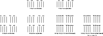
Figure 2: The Fabric Routeing Byte for each Slot
The slots are numbered by mapping the fabric routeing byte onto [0..15] as in figure 2

Table 2: Fabric Route Byte (in hex) to Slot Number Mapping