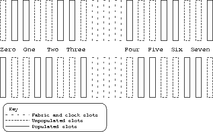
Figure 1: The preferred arrangement of connector positions
Each backplane contains connections for two separate 4 by 4 switches which are interleaved. The eight slots are labelled, from left to right, zero up to seven, zero, two four and six being connected to the left fabric and one, three, five and seven being connected to the right fabric. The left and right fabric slots and the clock generation board slot are situated between slots three and four. For a 16 by 16 switch two backplanes are needed (labelled upper and lower here). The PCB for the backplane is designed to allow a device to be plugged into a slot in the upper backplane whilst a different device is plugged into the same slot in the lower backplane. This is done by having two identical sets of holes in the PCB for sockets to be soldered into, but offset by 0.8 inches (the width of a device). Which of the upper or lower backplanes has which socket populated varies from slot to slot. This allows space for podules to be placed between port controllers in adjacent slots when the backplane is being used for a 4 by 4 switch. (see figure 1 for the preferred arrangement)

Figure 1: The preferred arrangement of connector positions
One backplane can only be used as two 4 by 4 switches. Two backplanes can be used as four 4 by 4 switches, two 8 by 8 switches or one 16 by 16 switch.
A single 4 by 4 switch can be constructed by plugging a 4 by 4 switch fabric into the left fabric slot of a backplane and devices into the even numbered slots. A separate switch can be constructed using the right fabric slot and plugging devices into the odd numbered slots.
A single 8 by 8 switch can be constructed by plugging a single 8 by 8 switch fabric board into the left fabric slot on the upper and lower backplanes and devices into the even numbered slots on both backplanes. A separate switch can be constructed using the right fabric slots and plugging devices into the odd numbered slots.
A 16 by 16 switch can be constructed by plugging two 8 by 8 fabrics into
the backplanes and connecting them together.
Devices can then be plugged into any of the slots.
When two 8 by 8 fabrics are connected, the BD signal becomes high on
one of them (the one with J3 populated). This alters the value fabric
routeing byte needed to route cells to the slots on that fabric board.
The preferred arrangement is to have the fabric with BD high in the
left hand slot ![]() .
.