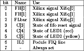
Table 2: IOC Control lines
The port controller interrupt and control lines for all devices are managed by the I/O controller (IOC). This provides two eight bit wide conventional interrupt (IRQ) mask registers, an eight bit wide fast interrupt (FIQ) mask register and a six bit wide control register.
The IOC control lines are used to control aspects of the xilinx chip, as detailed in table 2. The control register lines have pull up resistors on them so on reset, when they are undriven, they will go high. Thus a card reset will cause the fifos to be reset, and the strobe line to be deasserted. The top two bits of the IOC control register must always be set when the register is written.
The FIQ interrupt register which is described in table 3 contains three bits which are used by the Xilinx design and other general signals.

Table 3: IOC FIQ Status register
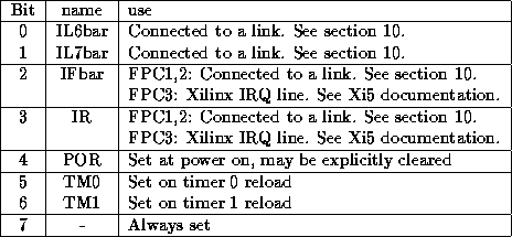
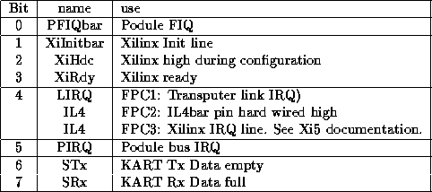
The IOC general purpose interrupt registers contain a mixture of external signals of which only some are meaningful on the port controller and some internal signals relating to the timer and console function also provided by the IOC. Interrupt status register A is described in table 4 and register B in table 5. The FIQ uses the ``Always set'' IRQ bit to post interrupts to the Wanda kernel.

Table 4: IOC Interrupt status register A

Table 5: IOC Interrupt status register B
Note that the podule FIQ line also appears in the IRQ register B should it be necessary to service a podule device which generates FIQ interrupts without complicating the xilinx FIQ software.