
ECAD and Architecture Practical Classes
| ModelSim 6.3a | |||
This tutorial gives a brief introduction to ModelSim. Like the SignalTap tutorial, this will make use of the params module of the pong project to illustrate the VGA timing signals. ModelSim is different to SignalTap since it performs a simulation of the design, rather than collecting the actual signals present on the device. Because of this, you have to add some code to intialise register values, and also produce a test harness for the module you wish to look at. Since it is a simulation, however, you have a lot more control over what you see, and the signals you give the test module.
A (much) more in-depth tutorial can be found on the PWF machines located in Y:\quartus71\Modeltech_6.3a\docs\pdfdocs\modelsim_se_tut.pdf.
Important: ModelSim does not like pathnames with spaces in them. Ensure that the pathnames to your working directories, together with the files contained in them, do not contain spaces.
Intialising registers
Open up the project in Quartus as usual, and then open the file params.v. Insert the following piece of code into this module:initial begin h = 0; v = 0; end
This will initialise the registers h and v to zero when the simulation starts.
Creating the test harness
Create a new Verilog file in the current project, and paste in the following code before saving the file as tparams.v.module test_params; reg clk; wire [10:0] x, y; wire vga_hsync, vga_vsync, can_draw, start_of_frame; // Instantiate the params module for testing params p( .clk(clk), .vsync(vga_vsync), .hsync(vga_hsync), .can_draw(can_draw), .start_of_frame(start_of_frame), .x(x), .y(y) ); initial begin // Initialise the clock to zero clk = 0; // Then at every 10th time unit, invert the clock // This generates the clock signal for simulation forever #10 clk = !clk; end endmodule
This forms the test harness for the module, providing it with a clock signal as described. If the module contained other inputs (such as a reset input) then you can create these signals in the same way as the clock.
Starting ModelSim
ModelSim is located in the Start menu under PWF Programs | Teaching Packages | Computer Laboratory | Quartus 7.1 | ModelSim 6.3a. If any dialog boxes pop up, close these until you get the screen shown below: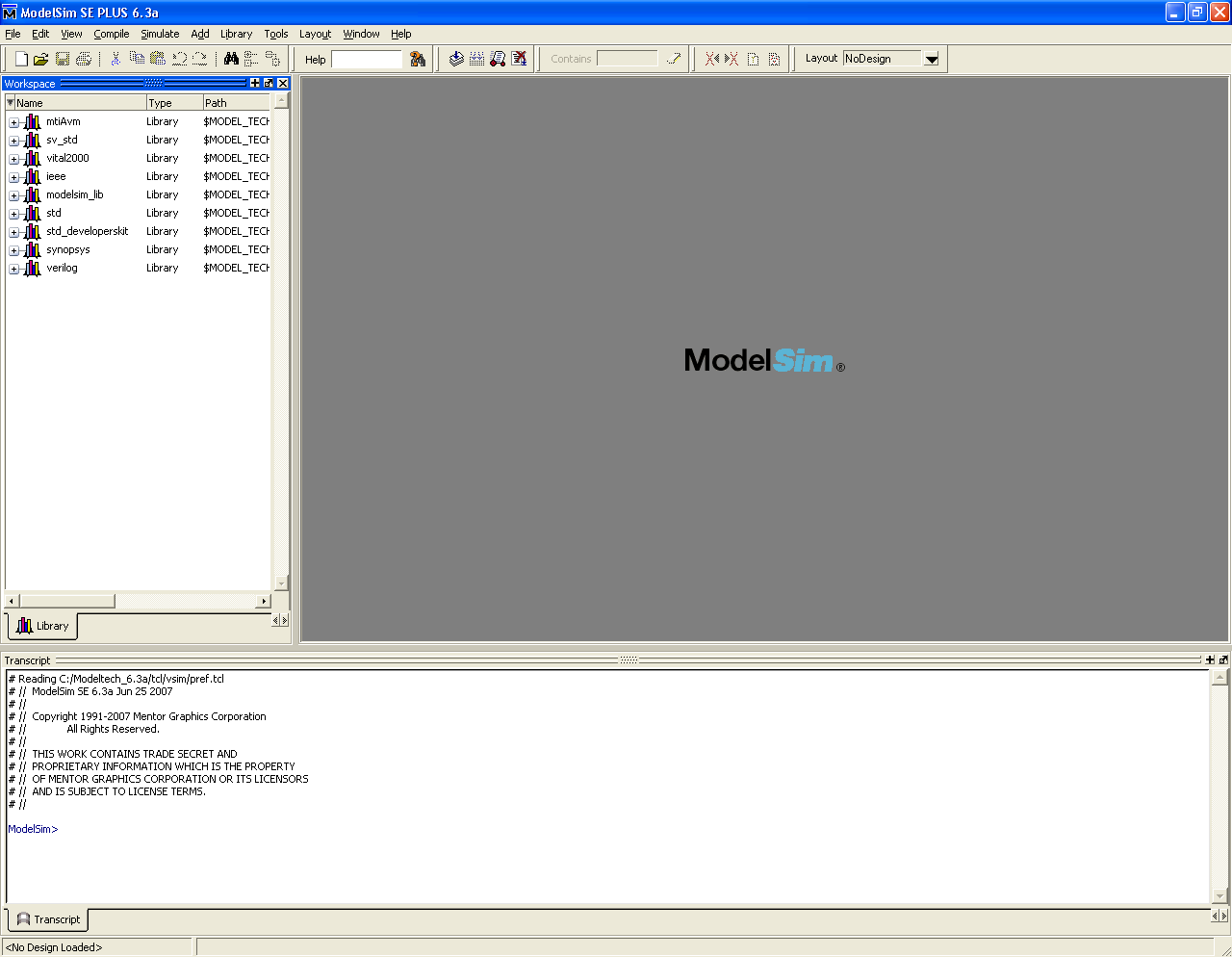
Creating a library
Before you can simulate any module, you first have to create a library containing the source files, and compile these within ModelSim.- First, set your working directory by selecting File | Change Directory.... The directory you select should be the one containing the verilog files for the project.
- Next, right-click in the workspace on the left hand side of the window, and select New | Library.... Type "pong" into both text boxes, and click OK. You should see this library appear in the treeview on the left hand side.
- You now need to compile the relevant Verilog files before they can be simlulated. Select Compile | Compile.... In the top
drop-down box, select the library pong, then select the files tparams.v and params.v. Click Compile.
Important: if ModelSim gives compiler errors mentioning undefined variables, or variables that are already declared in this scope, ensure you have declared all wires and registers before using them for the first time. Quartus doesn't complain if you use register names earlier in the file than they are declared, but ModelSim insists all registers and wires be declared before you use them.
Once you have compiled the modules, click Done.
Running the simulation
You can now run the simulation on the module test_pong to view the signals.You may have noticed when you have been creating libraries and compiling files several commands appearing in the window at the bottom of the screen. In general, anything that you can do with the mouse you can also type equivalent commands into the bottom window instead. This way, if you are performing several repetitive operations, or wish to automate the simulation for larger projects, you can create a tcl script (pronounced "tickle script") and run this.
To run the simulation for test_pong, type into the bottom window the command vsim -voptargs=\"+acc\" pong.test_params
You now need to select the signals you wish to view in the simulation as follows:
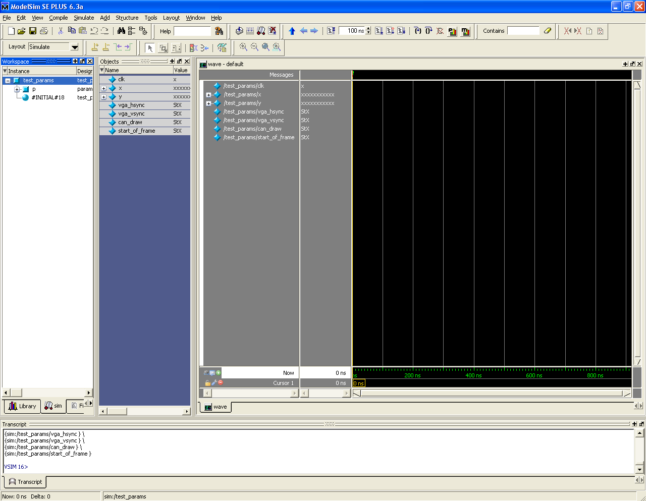
- In the workspace window, select test_params.
- In the objects window, which should now show the list of signals with the test_params module, select all the signals, right-click and select Add to Wave | Selected Signals. You should now have a window looking similar to the one below.
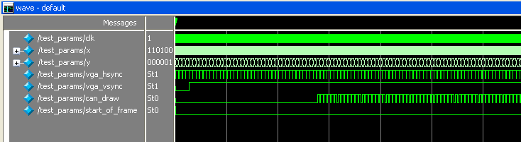
run into the bottom window. This runs the simulation for the default time of 100ns. In order to run it for longer, type
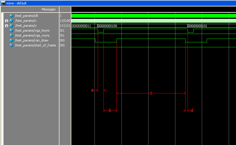
run time where time is the number of nanoseconds to run it for.Run the simulation for another 5,000,000 nanoseconds, and you should end up with some waveforms looking like the image below (use "+" and "-" to zoom in/out respectively within ModelSim).
That concludes the ModelSim tutorial. As you can (hopefully) see, ModelSim is alot more powerful than SignalTap as it allows you very fine grained control over the input signals from your test harness, and also allows you to view more signals for a longer time, rather than having a limited amount of on-chip memory with which to store signals.