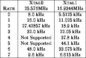
Since the hardware only contains a single digital video chipset, and a
single audio codec, only one physical input may be used at a time.
When using ``gen-locked''![]() video sources, it
is possible to multiplex the digitising hardware on a per-frame basis.
For audio this is clearly not sensible. The firmware therefore
supports multiple concurrent video streams,
video sources, it
is possible to multiplex the digitising hardware on a per-frame basis.
For audio this is clearly not sensible. The firmware therefore
supports multiple concurrent video streams, ![]() and a single
outgoing audio stream.
and a single
outgoing audio stream.
For each video stream it is necessary to download a number of parameters to the unit. These parameters specify picture sizes and scaling, pixel formats, data rates, the physical video channel to use and the VPI/VCI for the outgoing video stream. This information is loaded into a ``Video Bucket''. Similarly, parameters for the audio streams including sample rate, format and physical audio input must be loaded into an ``Audio Bucket''.
A ``Schedule'' is then loaded into the AVA200 which specifies a sequence of video buckets. This schedule is executed in a round-robin fashion, grabbing a frame using the parameters specified in the relevant video bucket. Thre reserved video bucket index of zero indicates that the unit should idle for a frame. The schedule also identifies which audio bucket should be used.
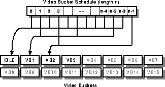
Figure 4: AVA200 Video Programming Paradigm.
These datastructures are shown diagrammatically in
Figure 4. The figure illustrates two concurrent streams
whose parameters are specified in Video Buckets VB1 and VB2. The
first stream is being allocated 3 frames out of every  , and the
second is receiving 2 frames out of every . The remaining frames
are being spent idling. Bucket VB3 has been loaded with the
parameters for a third stream in preparation for an atomic change of
schedule.
, and the
second is receiving 2 frames out of every . The remaining frames
are being spent idling. Bucket VB3 has been loaded with the
parameters for a third stream in preparation for an atomic change of
schedule.
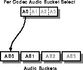
Figure 5: AVA200 Audio Programming Paradigm.
The audio paramters for each codec are selected from one of a number of Audio Buckets (see Figure 5). Since the AVA200 has only one codec, only the bucket referenced by channel A0 is examined. Audio buckets may also be loaded in advance (e.g AB1) in preparation for an atomic change of configuration.
The AVA200 uses AAL5 for all network I/O, although this may not be the case for the DAN implementation as the reliable nature of communications across the DAN remove the need for the added complexity of AAL5. Video formats used on the DAN may also take account of the unique properties of the Desk Area Network.
The AAL5 CRC32 field is not checked by the MPU on receive however, due to the complexity, so a simpler 16-bit checksum is used. The AAL5 CRC32 field is correctly generated for all transmitted PDUs however.
The receive side of the AVA200 control protocol consists entirely of single cell (52/53 byte) AAL5 PDUs. This is to remove the need for complicated reassembly functions on board the unit. The same format is used for both requests and acknowlegements.
Within this AAL5 PDU are various fields which are common to all control cells. A generic AVA200 control cell is structured as shown in Figure 6.
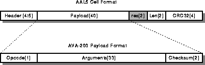
Figure 6: AVA200 Generic Protocol Cell.
The offsets of the fields within a cell are summarised in Table 1.
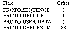
Table 1: Generic Protocol Cell Field Offsets
The various fields are described below:
 of the previous 38
octets XORed with
of the previous 38
octets XORed with  . The most significant octet is first.
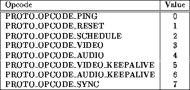
Table 2: Protocol Cell Opcodes
Sending a RESET cell to the AVA200 will cause all subsystems of the unit to be reinitialized. The management VPI/VCI for all future communications is specified in the cell. The acknowlegement for the cell contains version information for the hardware and firmware. The AVA200 RESET cell is structured as shown in Figure 7.
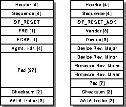
Figure 7: AVA200 Reset Cell and Acknowlegement.
The various fields in the RESET cell are described below:
Sending a PING cell to the AVA200 will cause the cell to be acknowleged without any further action. This is useful for checking the reachability and state of the unit. The acknowlegement for a ping request contains the same data as the request cell. The AVA200 PING cell is structured as shown in Figure 8.
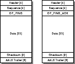
Figure 8: AVA200 Ping Cell and Acknowlegement.
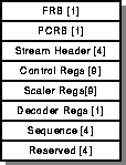
Sending a VIDEO cell to the AVA200 enables the loading of per-stream configuration into one of the 16 available buckets. The AVA200 VIDEO cell is structured as shown in Figure 9.
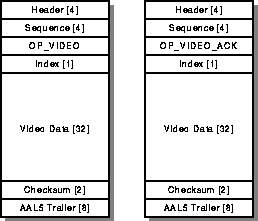
Figure 9: AVA200 Video Load Cell and Acknowlegement.
The offsets of the fields within the Video Bucket are summarised in Table 3.
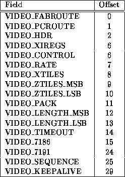
Table 3: Video Bucket Data Offsets
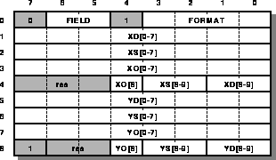
The INDEX field identifies which bucket is to be loaded. Only the least significant four bits are examined. The format of the configuration data to be loaded into the bucket is shown in Figure 10.
The video data consists of:
The fields in the Decoder registers have the following effects:
The fields in the Scaler registers have the following effects:
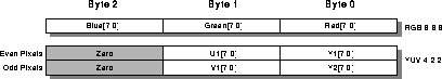
Figure 12: Pixel Formats output by the Scaler.
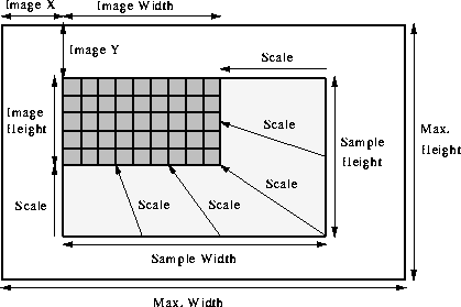
Figure 13: AVA Video Stream Sampling/Scaling
The fields in the control registers have the following effects:
 3210. This can be used to adjust the order of Red,
Green and Blue components to match the destination framestore.
3210. This can be used to adjust the order of Red,
Green and Blue components to match the destination framestore.
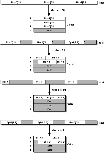
Figure: Effect of the MODE bits on the output pixel format.
Input format is set by the Scaler
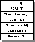
Sending an AUDIO cell to the AVA200 enables the loading of a new audio configuration. The data field of the AVA200 AUDIO cell is structured as shown in Figure 17.
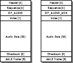
Figure 17: AVA200 Audio Load Cell.
The offsets of the fields within the Audio Bucket are summarised in Table 4.
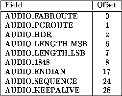
Table 4: Audio Bucket Data Offsets
The INDEX field identifies which audio bucket is to be loaded. The AUDIO DATA field consists of:
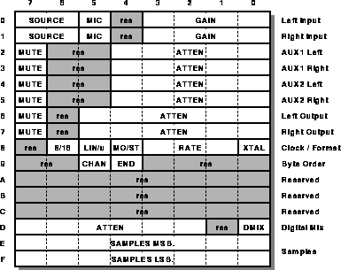
Figure 19: Audio Codec Registers.
The fields in the Codec registers have the following effects:
 of gain to the MIC input channel.
 .
.
.
.
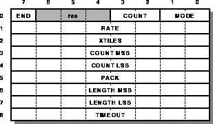
Sending a SCHEDULE cell to the AVA200 causes the audio and video schedules of the unit to be updated to those specified in the cell. The AVA200 SCHEDULE cell is structured as shown in Figure 20.
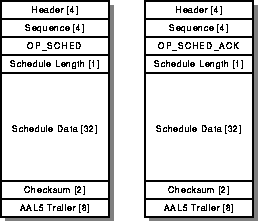
Figure 20: AVA200 Schedule Load Cell and Acknowlegement.
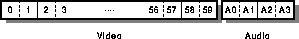
Figure 21: AVA200 Schedule Data.
At the end of every shceduling period (defined by the length field of the SCHEDULE cell), the AVA-200 sends a synchronisation PDU on the management VPI/VCI. This PDU contains the current sequence numbers of all video and audio buckets. The fields in the SYNC PDU are as shown Figure 22.
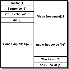
Figure 22: AVA200 Synchronisation PDU.
This feature is not present on some early versions of the unit.