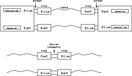
Figure 1: Cable colour code
It is important when connecting together two transmission boards, or a transmission and a Yes or Maybe board that no two transmitters are connected together. It is also important that no transmitter or receiver is connected to an Ethernet or video source both of which can use similar cable and connectors.
The cable protocol shown in figure 1 is designed to prevent this. On the end of each cable is attached a red and a blue strain relief (one on each end). Each transmitter has a blue socket (signified by a blue nut and washer holding the socket to the front panel). Into this the blue end of a cable should be plugged. Similarly, each receiver has a red socket into which the red end of a cable should be plugged.
When two cables are joined (by a barrel connector), the blue end of one cable should be connected to the red end of another.
The cable joining the transmitter on one board to the receiver on another and the cable going the other way are logically joined. In order to enforce this and to help differentiate the cables from Ethernet or video cables, they are physically joined. Shotgun cable (dual coax) is use and each cable has a red and blue strain relief on each end.