Table 1: Fabric Route byte (4 x 4 Fabric)
The switch fabric is a cell synchronous, crossbar switch. It is self routeing, that is, the cells have prepended to them routeing tags which tell the fabric which output the cell should be sent to (see figure 1). The routeing tags also contain priority information (in fact a single bit is used) which is examined when two cells contend for the same output. This tag is stripped off before the cell reaches the output stage.

Table 1: Fabric Route byte (4 x 4 Fabric)
Since the fabric (or indeed an output port controller) may chose not to accept a cell, an acknowledgement signal is provided. If the cell is blocked in the fabric, the input port on which the cell was injected will see a low on the acknowledgement line, otherwise it will see whatever the output controller chooses to respond with - in fact it is a clear return data path from output to input.
The job of the switch fabric is to detect cells, detect contention between cells, arbitrate between contentious cells, switch data between four inputs and outputs and to propagate or generate acknowledgement signals appropriately. Apart from the data and acknowledgement, the only other signal used is `frame start'. This is generated externally and is used to synchronise cells.
Figure 1 shows a schematic view of the switch fabric.
This section decodes the priority and routeing information from the fabric routeing byte. It generates 32 signals, 8 for each input - 4 indicating which output slot (if any) that input is requesting and 4 to indicate whether it is a priority request.
This section just filters out each input without priority which is vying with an input which has priority for the same output. These are then put into a 16 bit register - 4 bits for each input to indicate which output slot it is requesting access to.
This part of the chip detects an active bit from any of the inputs and enables the arbiter. It has 3 states (see figure 2) Run, Wait and Route. A frame start signal moves it from Run to Wait and an active bit from any slot moves it from Wait to Route. Any condition then moves the state machine back to Run. It remains in the `Route' state for just one cycle which triggers the arbitration unit.

Figure 2: State Diagram for Timing Circuit
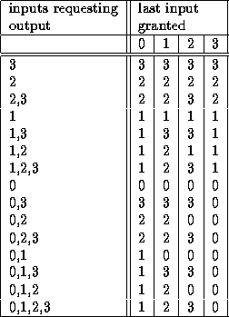
Whenever two or more cells contend for the same output of the switching element, arbitration takes places. Arbitration is done for each of the four outputs of a switching element. Each Arbitrater runs an independent round robin system. The inputs are numbered 0 to 3 and the last input to have a cell (of any priority) selected is remembered. If two or more cells contend, the last input which was selected is used as a base. The next input above (with suitable wrap around) the last selected is the one to be selected. Figure 2 shows which input is granted access to particular output given the last input granted access and the inputs attempting to gain access to that output.

Table 2: Round-robin Arbitration
The arbiter produces 4 two bit numbers determining which input each of the 4 outputs should copy. These are then passed to the data switch.
This is a simple multiplexer.
As soon as the arbiter has decided which routes are to be granted, this part of the circuit transfers the acknowledgement signals from the destination to the source of each route asynchronously or generates negative acknowledgements for inputs that have not succeeded in the arbitration process.
The data is latched at input and output. It is delayed one clock cycle whilst the decoding and filtering is being done and the data switch takes one cycle. The fabric routeing byte is stripped off, so the total delay from the start of a cell going into the fabric to the start of the (stripped) cell coming out is 5 clock cycles.
The switch fabric is built on a 4200 gate equivalent Xilinx programmable gate array. This, a serial PROM and 4 SIL resister packs (which pull-down all the inputs to each switch element for when a slot has no device attached) are the only components on a single height extended eurocard which plugs directly into a fairisle backplane. It can be clocked at 20 MHz and currently frame start pulses occur every 64 clock cycles.