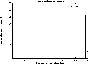
Figure 1: The periodic source - 4 back-to-back cells followed by 57 idle slots
Traffic generator were written for both the MIPS Maxine and the Fairisle Port Controller version 3.
The Maxine traffic generator allows the MIPS DecStation 3000/25 Maxine to be used as sources traffic for the BT experiments and was partly based on a benchmarking tool developed by Eoin Hyden. The Maxine contains a lot more memory than the FPC3 and therefore allows a much bigger trace file to be loaded. This is particularly important for large traces like the Bellcore "Star War" trace.
Building on an initial version by Steve Pope, the FPC3 traffic generator was developed by the authors to permit FPC3 port controllers to be used as sources of traffic for the BT experiments. The FPC3 is equipped with 4 megabytes of RAM, which permits it to hold a traffic trace, in the format described in section 4.1, of several hundred thousand blocks of cells. The maximum length of the trace will vary according to the size of the kernel used and the number of user processes spliced onto the kernel.
Both traffic generators consist of two parts. The first is a user space program which is responsible for loading traces to be transmitted, connecting to the remote sink, and initiating transmission. The user space process exports the traffic control interface described in section 3. This allows it to be controlled by a remote, Unix based user who is running an experiment.
The other part of the traffic generator is implemented in the Wanda kernel and is responsible for transmitting cells according to the trace data loaded by the user space process. It must accurately transmit blocks of data according to precise timings given in the trace.
The user space part of the traffic generator is a MSRPC-based process which exports the traffic control interface to allow Unix control programs, such as load, connect, start, to co-ordinate an experiment involving multiple sources, sinks and gateways.
The traffic source uses a single socket to represent the connection to the remote sink. It should be possible to extend the source to permit multiple connections to be made, and to send cells in the trace belonging to multiple connections. For the first release, however, the source makes a single connection to the sink.
The correct sequence of steps to follow in using the source is as follows. First instruct the source to connect to the destination Once this has been successfully achieved, instruct the source to load its data file. The source uses the Wanda dumb file system, documented elsewhere in this collection. This presents the source with a standard Unix file interface to the trace file, which is located and managed by the WDFS. The appropriate hostinfo must be supplied to the source to permit it to contact the WDFS.
When reading its trace file, the source allocates a segment of memory large enough to hold the entire file. Normally the FPC3 source can load up to 800000 blocks of trace data. For the Maxine in the Computer Laboratory which has 40MB of memory, trace files of 18M blocks should not cause any trouble. Each of these represents a pause and a single block of cells.
The source can load several data files in succession. After transmitting a file, if a new load command is received, the old trace data will be discarded and new data loaded. The source should thus survive several sets of experiments.
Once the source has read the trace file, it can be instructed to start transmission. At this point the source will send commands to the kernel-based generator to instruct it how to transmit the cells.
Communication between the source and the kernel-based generator varies according to the machine architecture that the generator is based. Note that both mechanisms only work with SAS Wanda.
For the Maxine version, the communication is done via the misc fields of the WandaIOBuf structure.
There is a distinction between the normal trace source data and the "Star War" trace. "Star War" trace is treated specially for two reasons:
The code has been specially tuned to produce the specific timing, i.e. 1.4ms per slice of data.
Various playout methods of the "Star War" trace data are allowed, e.g. each slice as a burst, even-spread of data over the slice time etc. Generating a normal trace file format for some of these playout strategies will simply generate enormous trace files.
The user space program can also specify the payload by filling data in the WandaIOBuf. In the current implementation, the first cell worth of data is sent repeated at the timing specified by the trace data.
For the FPC3 version, the communication is via control operations on the socket connecting the source to the sink. These take the form of WandaIPCControl calls on the socket, which are delivered by the ioctl control function of the Fairisle device driver to the kernel-based generator. It is imperative that the source first connect to the sink, so that the connection is routed via the Fairisle device (either transmission or fabric pod), before any control commands are given to the kernel-based generator. Failure to do this will result in commands being rejected by the kernel.
The protocol used for communication is as follows:
The WandaIPCControl call is issued on the socket with an I/O buffer as argument. The I/O buffer should contain:
The kernel section of the MIPS Maxine traffic generator consists of a special version of the YES driver. Upon recognising a particular WandaIOBuf is from the traffic generator's user space program, the kernel section takes control of the YES driver and executes special cell transmission code.
The YES driver first extracts the parameters for the particular trace from the WandaIOBuf and pre-format the cell buffer with data in the WandaIOBuf. It then executes in a tight loop, reading successive entries from the trace data, until it has finished sending the trace.
Figure 1 shows the inter-arrival time distribution for a stream of cells transmitted by the MIPS Maxine source. The trace is periodic with 4 back-to-back cells followed by 57 idle slots. There is some drift in the performance, but the source is largely accurate.

Figure 1: The periodic source - 4 back-to-back cells followed by 57 idle slots
The kernel section of the traffic generator has privileged access to the Fairisle interface, does ghastly things with the FPC3's buffer pool, and excludes all other threads of control from the CPU until it has finished sending the trace.
The kernel part of the traffic generator consists of several parts: a modified Fairisle device driver fair5.c which is exactly the same as the conventional, current Fairisle device driver except that the default number of ATM buffers which are maintained for the local Wanda system has been reduced to permit more buffers to be used by the generator, a modified fiq interrupt handler fiq5.s in which the priority of the service for traffic leaving the local Wanda system has been made the highest priority, above that of traffic which is being routed through the port from the transmission interface (it has been assumed that this will not occur), and a thread which manages the transmission of cell blocks from the loaded trace file.
The files supplied as part of the generator are slot in replacements for the same files in the Wanda kernel, as of the time when they were written. The additional file, xi5tgen.c, and its associated header file xi5tgen.h, should be built in the Wanda kernel, in the machdep/arm subdirectory. These two files constitute the body of the generator. The header file defines the format of each trace entry. This is described in section 4.1. The code is structured as follows:
A single function, the tgen_callback function, is called by the Fairisle ioctl function to pass commands to the generator. The arguments to the command function are the command and the argument. The command and argument are extracted from the I/O buffer by the ioctl function in the Fairisle driver. For each command other than ``start'', the appropriate static variables for the generator are set, these include the pointer to the trace data, the size of the trace data, and the vci to use. When the start command is issued, the other variables used by the generator must already have been initialised. When the start command is given, a thread is forked to transmit the trace data.
The transmission thread assumes control of the entire machine. First, it allocates a large pool of buffers from the FPC3's ATM cell buffer pool, for use when sending data. These are kept in an array of buffer numbers, indexed by a free buffer counter.
The transmission thread disables interrupts and reads the xi5 free
running clock to establish the current device time. It then enqueues
its buffer pool on a private queue which has an identical structure to
the queues used by the fair5 device driver and fiq. It then reads the
device time again, and computes the average time for an enqueue
action. This permits the code to be self monitoring in terms of its
own execution time. The same procedure is followed for dequeueing, to
gauge the time to remove a buffer from a queue. These values are
printed for your reference. They should be approximately 1 time unit.
At the time of writing a single Fairisle time unit is 1/64 of the
fabric cycle time, which at 20MHz is approximately 3.45  .
Remember that the fabric units are influenced by the fabric clock
speed, and therefore all time measurements are relative to this.
Having calibrated itself, the generator selects a random entry point
in the trace and enters a loop in which a single trace entry is
transmitted per iteration. Each trace entry consists of an idle time
followed by a number of cells transmitted back-to-back. At the start
of each iteration the generator writes a value, representing its idle
time in fabric cycles, to the Xilinx timer clock, TC. This clock
raises an interrupt whenever it reaches 0. It decrements by 1 unit
every clock cycle. Recall that the generator has already disabled all
interrupts. It therefore needs to periodically poll the timer to
check whether the time has expired. During the idle time the
generator must ensure that it replenishes its buffer pool. Buffers
requested from the Xilinx are delivered via the queue called the bads_queue. The generator continuously attempts to remove cells
from this queue or the arriving_queue containing cells
transmitted to the local system (this will include all signalling,
meta-signalling and other traffic). After each action it checks to see
whether it is time to send more cells. If the timer clock has
expired, then the generator enqueues  cells on the Fairisle device
leaving_queue which is used to transmit data from the local
system. Interrupts are off, so none of the cells are transmitted.
Once the block has been enqueued, the generator turns on fiq
interrupts to request the fiq to transmit the block.
Recall that the time taken for each enqueue step has been measured during calibration. Also, the time taken to transmit a cell can be safely assumed to be one clock unit. The time to transmit the block is thus the enqueue time plus the transmission time. For each cell transmitted, the generator requests a cell buffer to replace the transmitted cell, up to a limit, named DELTA. The generator goes to great lengths to ensure that it maintains a balanced pool of cell buffers, managing stochastic fluctuations in the pool size by keeping track of how many buffers are required and how many have been requested from the Xilinx.
Having sent the block, the generator reads its next trace element, and computes the idle time before the next block. This is the idle time specified, less the enqueueing and transmission times for the block (see above), and a heuristic value which measures the time taken for this code to execute. The generator takes care to ensure that if very little time remains before the next block, that it begins transmission at the correct time. It then decrements a counter of the number of entries to transmit, and repeats the loop.
When it has finished sending the whole trace, the generator frees its buffer pool and prints the number of cells which it sent, and the number, if any, that it was unable to send before their deadline.
Interrupts are restored, and the machine should function normally once again.
Because the generator has to recover buffers from the Xilinx in order
to continue transmission, and each buffer retrieval takes about 1
clock tick, the source should never be used with a trace which has an
aggregate mean bandwidth requirement of greater than half of the
fabric bandwidth. Also, it needs time to recover buffers per block,
otherwise in the long run it will deplete its buffer pool and be
unable to maintain the required transmission behaviour. I have
successfully used the source with traces which use up to one third of
the fabric bandwidth. I doubt that it will cope with much more.
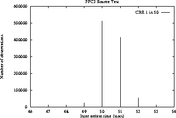
Figure 2 shows the inter-arrival time distribution for a
stream of cells transmitted by the FPC3 source. The trace is periodic
with 1 cell followed by 50 idle slots. As
can be seen, there is some drift in the performance, but the source is
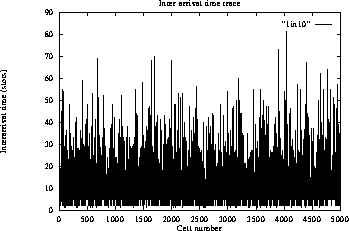
largely accurate. Figure 3 shows the trace of the
inter-arrival times for a sequence of cells transmitted by a Bernoulli
source which has a mean bandwidth requirement of  of the fabric
bandwidth.
These measurements have been taken using experimental queueing and sampling code written by the author.

Figure 2: The periodic source - inter-arrival time distribution

Figure 3: Bernoulli traffic - inter-arrival time trace