⇡ Tutorial for the v0.4 lowRISC release
Overview of the minion infrastructure
As part of the lowRISC project we are exploring how simple processors (minions can help define an SoC’s functionality including some I/O interfaces. We invisage tailoring these cores depending on where they are used and also providing a thin layer of additional logic to help interface between the core and the signals it is driving or monitoring (we refer to this as the shim logic). This release includes a simple minion subsystem to help us explore some of these ideas. In theory multiple Minions could be used, but to meet the objective of supporting the same FPGA platform as before, only one Minion, which is dedicated to vital I/O tasks, is provided.
“In this picture…” -> I think the message is that the n is nearly complete and that we’ve taken a step forward in supporting the idea of minion cores. Not that the minion core system is the “main topic of this tutorial” (i.e. the whole tutorial)
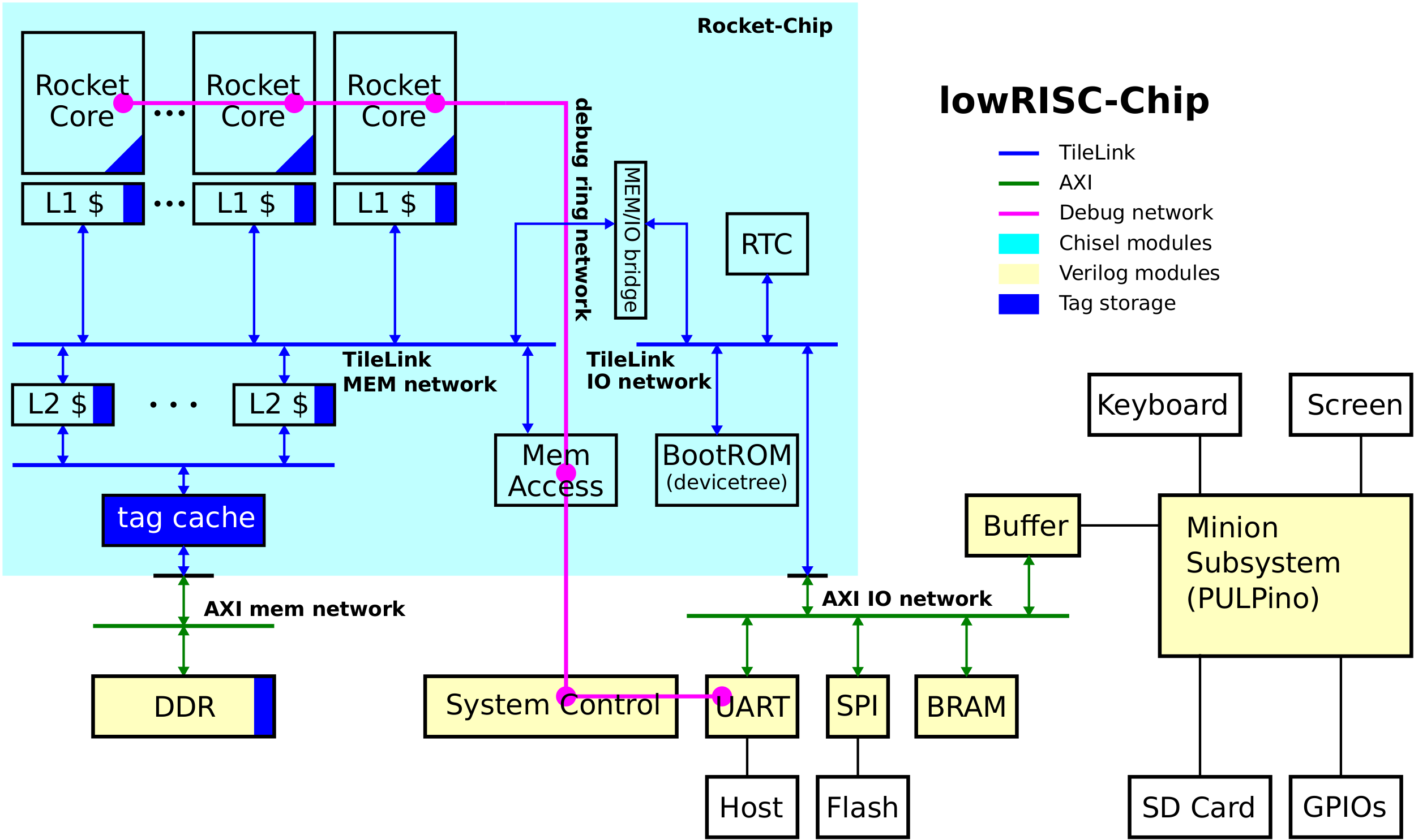
In the picture below you can find an updated overview of the lowRISC system architecture. If you compare it to the previous SoC overview you can see that the major change is tagged memory implementation and the new minion infrastructure.
Pre-defined Design constraints
Our goal of supporting the same FPGA board as the previous release may only be realised with a single Minion, due to logic area constraints. Nevertheless it is conceived that a fully-fledged system would make use of several Minions. The Minion processor is based on a cut-down version of Pulpino, a RISC-V compatible processor from ETH Zurich. THis Minion is intended to off-load some input/output tasks from the Rocket.
For example, memory card access previously used the AXI infrastructure and SPI IP from Xilinx to boot and access the card under Linux. The SD-card interface is eventually intended to be a software re-programmable input/output device incorporating programmable shift registers as well as direct CPU control. To re-create the previous functionality, it was necessary to provide a backward compatible interface to be used to allow Linux to boot from a small on-chip memory.
This chicken and egg scenario is solved by making use of a fixed I/O shim in this release.
To take advantage of the 4-bit mode of operation available with modern SDHC-cards, a simplified SD-subsystem from the opencores sd_card_controller project was adapted for use with the Minion. The enhanced system including processor takes approximately 1⁄6 of the FPGA. Some aspects of the operation of these cards are obscure. It is desirable to refer to older documents such as the MMC card specification for clarification of missing information.
Overview of the boot process
To economise on silicon area, most systems nowadays make use of a large volatile off-chip memory, such as mobile double-data rate(DDR) dynamic memory, together with a small on-chip ROM. This concept has hardly changed since the PC-bios was introduced in the 1980s. The economies of scale come from the specialised architecture of the DDR memory. A size of 64K is usually considered adequate for a boot program. In the FPGA context something larger would take resources away from useful subsystems such as caches and Minion program memory. By contrast, for non-volatile memory, NAND flash is the market leader by volume, and especially prevalent in secure-digital(SD) cards, where the flash is combined with an intelligent controller (which also results in variable latency).
To take control of the SD I/O process using the Minion, the boot process that was previously used needs to be duplicated and modified. The SD-card protocol requires a 119-bit command shift register, together with 512-bit (minimum) data FIFOs. The long history of development of media cards requires an elaborate initialisation sequence. For purposes of booting, this is replaced by a fixed sequence. The consequence of this is that, although Linux supports all kinds of SD-cards, the system can only boot from Micro-SDHC cards capable of 5MHz operation (the majority of those now available).
To avoid using the SPI mode of the SD-card, a lengthy sequence of inquiry packets needs to be sent to establish the SD-card capabilities. Users should avoid using the onboard PIC processor to configure the bitstream in SPI mode. This will result in difficulties returning to SD-mode later. Alternatives available are USB memory stick (if the built-in keyboard is not needed), or on-board Quad SPI flash. The Rocket chip has only 64K ROM (implemented as block RAM) allocated to the boot process. A full-blown SD-card protocol stack would be many times this size, so we make many simplifying assumptions about the technology of the card which will be used. Essentially it needs to be Micro-SDHC, with a fixed 5MHz initialisation and operating frequency.
The initialisation is:
- Cmd0 (reset)
- Cmd8 (send interface condition)
- ACmd41 (send operating condition)
- Cmd2 (send card ID)
- Cmd3 (send relative card address)
- Cmd9 (send card-specific data)
- Cmd13 (send status register)
- Cmd7 (select card)
- Acmd51 (send SD configuration register)
- Acmd6 (set bus width)
- Acmd13 (send SD status)
Assuming no errors occured, sector read can proceed with Cmd16(set block length) followed by Cmd17(read single).
All commands have a command phase, some also have a data phase, for more details consult the SD Group physical layer specification.
Within each relevant command an elaborate data phase provides longitudinal CRC checking and error recovery. A future enhancement could add the intelligence for multi-block random access during booting.
Boot file system
The boot file system only supports a single DOS partition, which has to be partition 1. It does not support writing to the card. Most modern SD-cards out of the box will meet these requirements. Under Linux the available facilities are much more sophisticated, and a second ext2 partition with extended userland commands can happily coexist with this boot partition.
FPGA boards, by their very nature, are noisy environments so it is desirable to be able to check the contents of the second stage boot loader after reading it from card. The builtin ROM can read an md5 text file and compare its contents with the calculated value on the second stage boot loader. The remaining task is to extract the ELF segments for the Berkley Boot Loader (BBL), and the kernel itself to their respective locations in memory, before the boot process proper can begin.
Future minion developments
This release incorporates a ‘minion’ core for the first time, but there is of course much more to be done. In the future, we want to integrate support for a programmable ‘shim’ that would allow minions to be used in a flexible way for programmable IO, to have the minion control the boot process, and to stabilise the interface between the minion and application cores.
Please get in touch with us if you have ideas and opinions about future directions we should take. Now it’s time to learn more about the debug system or jump into using it: