⇡ Tutorial for the debug preview of lowRISC
Working with Zedboard
lowRISC was ported to Zedboard in KU Leuven - COSIC to design and verify trusted computing hardware extensions
Porting lowRISC to Zedboard
Zedboard is versatile development board utilising Zynq SoC. It has been used in several implementations of RISC-V; hosting it as a neighbour to the Zynq’s hard-coded ARM cores. However, in Zedboard the ARM cores of the Zynq are dominant: almost all peripherals or ports connect to the ARM Processing System (PS), and they are not directly reachable from Programmable Logic (PL). That makes the RISC-V, implementated in PL, inaccessible without passing through the ARM PS. Therefore, the RISC-V implementations for Zynq (including the original release by Berkeley or the earliest lowRISC design) use so called Host/Target Interface (HTIF), which has the front-end server running on PS and communicating with the target RISC-V implemented in PL, which is the tethering of RISC-V to ARM.
Compared to the other RISC-V implementations, lowRISC’s achievement of offering an untethered RISC-V implementation is great; however, made the design leave the Zynq devices initially. However, with the implementation described in this page, the Zedboard support is added again. Zedboard’s SD Card and UART ports are connected directly to ARM; therefore, the port of lowRISC to Zedboard requires obtaining two low-cost PMOD modules to provide RISC-V with dedicated IO, and continue working untethered.
- For SD Card: Pmod SD
- For UART: Pmod RS232 or Pmod USBUART
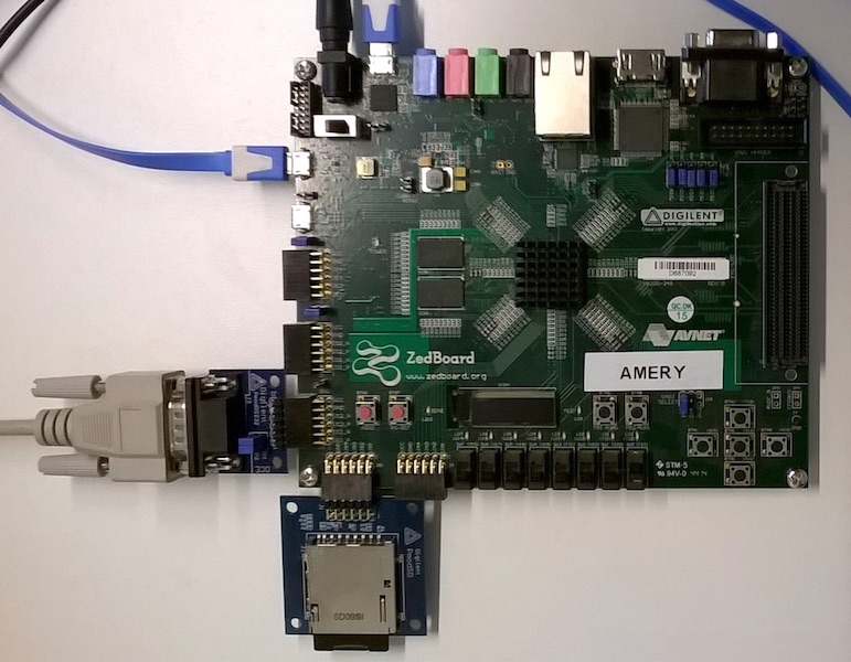
Together with the PMODs, the board looks like it is in the image below:
Dedicated IO is provided to RISC-V with PMODs; however, the Zedboard has a single DDR RAM, and it is connected to the Zynq SoC through the memory controller of ARM PS. Therefore, in this Zedboard port of lowRISC, the RISC-V accesses to memory through the ARM PS. In other words, the memory is shared between the ARM and RISC-V cores. The chip-top.v file is expanded to make nasti memory port of RISC-V accessible as module IO, instead of connecting it to MIG IP Core as other board implementations do. On top of this, a block diagram is provided which instantiates the ARM PS7. Finally, Wrapper.v is provided as the top-design file, which connects the ARM PS7 and RISC-V. This connection manages clock and reset signals, and connects the RISC-V nasti memory port to the PS7’s memory controller through HP0 AXI port.
A great outcome of this port is one board with two systems on same chip; one of which is ARM, the most accepted architecture for embedded devices, and the other is RISC-V, the most promising. Once can configure to run them independent of each other, and establish shared memory communication as they physically share the memory.
The Tutorial on Working with Zedboard
Preparation
Get the lowRISC development environment.
git clone -b debug-v0.3 --recursive https://github.com/lowrisc/lowrisc-chip.git
cd lowrisc-chip
Now you need to prepare the environment as described here
- If you haven’t before, compile and install RISC-V cross compiler
If you haven’t before, install Vivado and set your environment Note: The Zedboard port is implemented with Vivado 2016.2
Set environment variables:
export FPGA_BOARD=zed
source set_env.sh
Implement the FPGA Project
Go to the Zedboard submodule.
cd $TOP/fpga/board/zed
Before continuing, make sure that you have the correct pin mapping of your PMOD connections in the $TOP/fpga/board/zed/constraint/pin_plan.xdc file. In the default configuration (above image), PMOD SD is connected to JB headers of the Zedboard, and PMOD RS232 is connected to the (upper pins of) JC headers. If PMOD USBUART is preferred, as it is not pin-to-pin compatible with the RS232, comment the RS232 mapping lines on the pin_plan.xdc file, and uncomment the lines for USBUART.
As the work environment is ready, you can work with make targets:
| make target | description |
|---|---|
make verilog |
generates the FPGA backend Verilog files |
make project |
generates the Vivado project |
make vivado |
opens the project in Vivado GUI |
make bitstream |
generates bit-stream for programming. |
make program |
programs device. |
make search-ramb |
finds out the boot BRAMs’ name and position (for updating src/boot.bmm). |
make bit-update |
replaces the content of boot BRAM with a new src/boot.mem (must update src/boot.bmm first). |
make program-update |
programs the device with updated bitstream. |
make boot, make hello, ... |
compiles the example codes in $TOP/fpga/bare_metal/examples, and automatically executes make bit-update for the compiled. |
“Hello World!” from RISC-V
To receive the friendly welcome message, execute hello and program make targets sequentially. The first make target will compile the hello code in $TOP/fpga/bare_metal/examples/ for RISC-V ISA, then load it to BRAM of the design which stores the user code that will be executed first. Next, the design will be synthesized, implemented and corresponding bitstream will be generated. The second make target is to program the device with the generated bitstream.
make hello
make program
To receive RISC-V’s terminal dump, a serial terminal should be running for the UART port associated with the PMOD module. You can use microcom, which is the recommended serial terminal application:
microcom -p /dev/ttyUSB0 -s 115200
Booting Linux on RISC-V
Above this subtitle, setting the environment, generating hardware, and programming the device were introduced. For booting Linux, the same procedure will be followed, except the change in the target RISC-V application. Instead of hello, the boot target will be used. This target sets the BRAM with bootloader as the first user application. The bootloader opens SD Card (from the PMOD), reads Linux image from there, copies it to memory and hands over hardware’s control to it.
Before jumping to program RISC-V for booting Linux, prepare the SD Card with the Linux image.
Build Linux
Build the port of Linux kernel for the RISC-V instruction set architecture as described here:
cd $TOP/riscv-tools
curl https://www.kernel.org/pub/linux/kernel/v4.x/linux-4.6.2.tar.xz | tar -xJ
curl -L http://busybox.net/downloads/busybox-1.21.1.tar.bz2 | tar -xj
cd linux-4.6.2
git init
git remote add origin https://github.com/lowrisc/riscv-linux.git
git fetch
git checkout -f -t origin/debug-v0.3
# lowRISC-specific hack for enabling power pin for SD card
patch -p1 < spi_sd_power_hack.patch
cd $TOP/fpga/board/zed
$TOP/riscv-tools/make_root.sh
Copy the generated $TOP/fpga/board/zed/boot.bin to SD Card.
Program RISC-V with Bootloader
As it was for the hello, execute boot and program make targets sequentially.
make boot
make program-updated
Finally, you will see Linux initialise with the dump like:
lowRISC boot program
=====================================
Load boot.bin into memory
Load 5563024 bytes to memory address 87000000 from boot.bin of 5563024 bytes.
load elf to DDR memory
Boot the loaded program...
              vvvvvvvvvvvvvvvvvvvvvvvvvvvvvvvv
                  vvvvvvvvvvvvvvvvvvvvvvvvvvvv
rrrrrrrrrrrrr       vvvvvvvvvvvvvvvvvvvvvvvvvv
rrrrrrrrrrrrrrrr      vvvvvvvvvvvvvvvvvvvvvvvv
rrrrrrrrrrrrrrrrrr    vvvvvvvvvvvvvvvvvvvvvvvv
rrrrrrrrrrrrrrrrrr    vvvvvvvvvvvvvvvvvvvvvvvv
rrrrrrrrrrrrrrrrrr    vvvvvvvvvvvvvvvvvvvvvvvv
rrrrrrrrrrrrrrrr      vvvvvvvvvvvvvvvvvvvvvv
rrrrrrrrrrrrr       vvvvvvvvvvvvvvvvvvvvvv
rr                vvvvvvvvvvvvvvvvvvvvvv
rr            vvvvvvvvvvvvvvvvvvvvvvvv      rr
rrrr      vvvvvvvvvvvvvvvvvvvvvvvvvv      rrrr
rrrrrr      vvvvvvvvvvvvvvvvvvvvvv      rrrrrr
rrrrrrrr      vvvvvvvvvvvvvvvvvv      rrrrrrrr
rrrrrrrrrr      vvvvvvvvvvvvvv      rrrrrrrrrr
rrrrrrrrrrrr      vvvvvvvvvv      rrrrrrrrrrrr
rrrrrrrrrrrrrr      vvvvvv      rrrrrrrrrrrrrr
rrrrrrrrrrrrrrrr      vv      rrrrrrrrrrrrrrrr
rrrrrrrrrrrrrrrrrr          rrrrrrrrrrrrrrrrrr
rrrrrrrrrrrrrrrrrrrr      rrrrrrrrrrrrrrrrrrrr
rrrrrrrrrrrrrrrrrrrrrr  rrrrrrrrrrrrrrrrrrrrrr

       INSTRUCTION SETS WANT TO BE FREE
[    0.000000] Linux version 4.6.2-gb370a4b (fturan@soorske.esat.kuleuven.be) (gcc version 6.1.0 (GCC) ) #27 Tue Mar 7 10:29:24 CET 2017
[    0.000000] Available physical memory: 122MB
[    0.000000] Initial ramdisk at: 0xffffffff800172c0 (759029 bytes)
[    0.000000] Zone ranges:
...
...
...
#
You can continue with working on Linux by mounting SD Card as it is described here.
Remarks on Programming
It is important to understand that the Zedboard consists of two parts; ARM Processing System (PS) and Programmable Logic (PL). Programming only the PL with the lowRISC implementation is not enough since the implementation depends on PS for the clock, reset and the memory controller; therefore, the PL needs PS to be initialised. To solve this problem, make program initialises the PS using a pre-set file $TOP/fpga/board/zed/helperscript/ps7_init.tcl. This file is an SDK generated file for its the default Hello World application project. Of course, one may prefer to run his/her own code on ARM instead of just initialising it, and program the PS according to. In such a case, it is possible to program both the PL and PS using SDK either at design-time, or automatically from SD card (not from the PMOD, but Zedboard’s built-in socket) at power-on.